LSMITH
-
Posts
16 -
Joined
-
Last visited
LSMITH's Achievements
")
Block (2/9)
1
Reputation
-
Transfer intellishape depth to 2D drawing for DXF export
LSMITH replied to LSMITH's topic in General Discussion
Thanks Jonas, I do reuse parts and panels and have catalogs for my reused parts and such so I do have a lot of things memorized. I'm the one who programs the files for CNC anyway so I don't usually have to call these things out. I have another guy who does this as well and we're about to train a new person so eventually I'm hoping I won't be creating the actual CNC files for much longer so this would help give those details to whomever is. Mostly what this would be used for (the depth callout) is on unique items where I'm slotting pieces of plywood together to minimize the assembly time. When someone doesn't have to measure off, mark, place, and staple and can instead put the panel in the slots and know that it's exactly where I want it to be, saves a ton of time. I also have some situations where I have to bury a threaded insert flush to a piece of ply so it can be sandwiched against another. These depths can sometimes change depending on the part used. I tried the parameter method yesterday, creating a depth parameter from the hole block intellishape but didn't experiment with the best way to get that mapped to the drawing. Adding a custom property from the sizebox info was a hassle because it has to be edited once it's added in order for it to turn from "=Shape2\Sizebox\Height" to 0.25 but I didn't try getting the parameter itself to map. I'm sure I could set a hole block in a catalog that already has that parameter in place and would update as a reference when changed. The sizebox property would be an issue too because the shape number would change depending on where in the process it was added. I'll give the parameter method a shot and see how that goes mapping to a title block or something. For the drawing, when doing the flat files for CNC, I usually have all parts for one "unit" of the project being in one view. That way when I drop a view into the 2D drawing all of the parts for that unit are grouped together. This helps when exporting to DXF because I can add the Name or a Note to the view to help keep me organized when in Enroute adding the part numbers to the pieces which I typically have to do manually. I'm experimenting with a custom BOM and item bubbles with no frame, knee, or leader that I can associate to each part in the view. Even if I have to add the numbering manually again in Enroute since I can't rotate the item bubbles vertically. I've messed around a little with the front view orientation per part but in order to do a bulk drawing and have a sheet for every part means each piece has to be exported to DXF and imported one by one in Enroute. Having one page with all of the views on it that I can export and import as one file with names of the units speeds things up a bit. I only use the flattened configuration for exporting 1:1 DXF's and that page isn't one that's added to a package for the fab shop. -
Transfer intellishape depth to 2D drawing for DXF export
LSMITH posted a topic in General Discussion
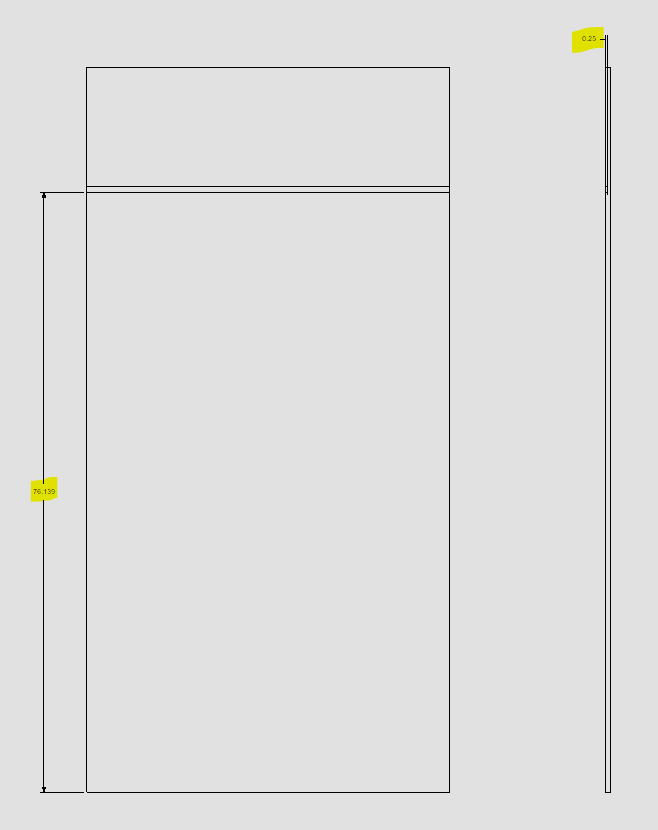
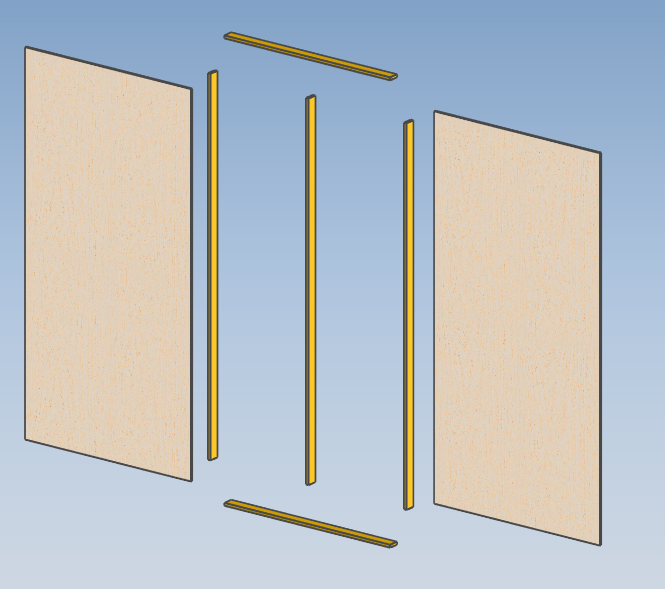
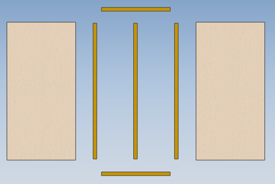
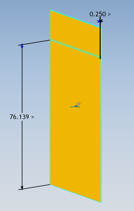
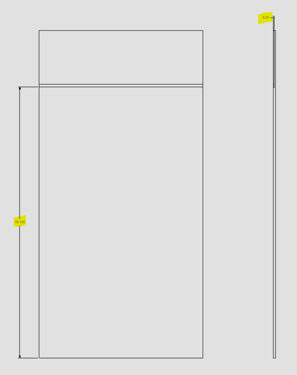
Is there a way to transfer the depth of a pocket in a part to a 2D drawing or DXF export to be sent to CNC tool pathing? After exporting DXF's of panels that have slots or pockets cut in them that do not go all the way through the panel, I will always have to come back to the 3D scene to find out exactly what the depth was in order to set that depth in the tool path. Is there a way to automatically have the depth of a pocket or intellishape be transferred to the DXF or to the 2D drawing to be exported to DXF? I've tried using the smart dimension but it will not show in the front view if the depth is going the same direction. I can add a PMI annotation but I still have to manually type it in versus having it populate. It would be nice to have a tool like the hole callout tool that will automatically give the depth. Is there a way to automatically have an intellishape create parameters when it's dropped that could be mapped to custom properties of the part and display them in a BOM type of table in the drawing? Smart dimensions shown in 3D: Transferred to drawing in 2D view only in certain orientations: Just looking for ways to increase the speed and efficiency when detailing for production. Speaking of efficiency, is there any way to "flatten" every part in a configuration so that the Z value is facing the same direction or to have selected faces all facing front without having to use the triball to rotate each piece individually or using the Positioning tool to move? Sort of like the 'ICMech-Create exploded' tool will expand everything either from center or z direction, you could select every face you want to be pointed towards front and then apply to flatten in one move. Example below: Panel assembly- Exploded- Flattened for export- Thanks all -Logan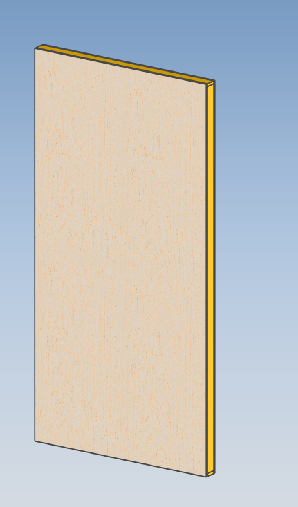
-
So far as I can tell, unless I'm doing something wrong, using the template check mark in the layers pallet doesn't affect each sheet individually. I made sure the items were on the template layer and that check mark was selected and then saved the drawing as a template. Created a new drawing from the template and tried different methods for new pages: Right clicked on the sheet name and copied to the end and inserted a new page from the template file. When editing an element on the template layer, it does not carry over between sheets. I also edited an item and then added a new sheet from the template and it still brought in the original instead of linking to the one already there. Copying the sheet brings everything with it but changing an element on one sheet doesn't affect any others. Any suggestions to make that work that I may be doing incorrectly?
-
Thanks Kevin, I'll give that a try on my next drawing and report back. We've been working with basically the same template for years and I've made some changes to make it auto fill different properties but most things have just been left alone, that being one of them.
-
Hey Kevin, will using the template check box in the layers menu allow for objects and items to be used on every page of the drawing file? For instance a company logo. I had to go and change how our logo was added to the sheet so it would export cleanly but I had to copy and paste this onto each sheet in a drawing with 25 pages. Would having it on a template layer with the template button checked make it so replacing it once would replace it on all sheets?
-
This answers the question I had below about which configurations needed that intellishape selection to be made on. I knew intellishape changes always tracked between configurations for us but didn't stop to realize that the assembly features would be acting in the same way. Thanks for the video sir.
-
Hi Malcom, I appreciate you putting together the explanation and videos for me, that'll be a big help. I haven't watched yet but would that "track intellishape" option need to be selected for ALL configurations or just the one that it's been created in? As for the CAXA vs ICD, I'm going to read through these and see if it makes sense to try to change the process. We have several people who use ICD so it would be pulling teeth to get everyone to try to switch to a completely new process while we're still perfecting the one we have but I have no problem if it makes sense for me. Thanks again, -Logan
-
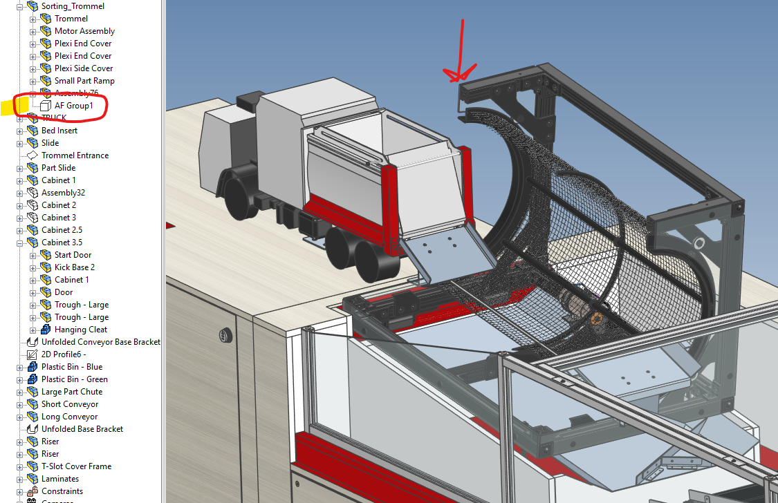
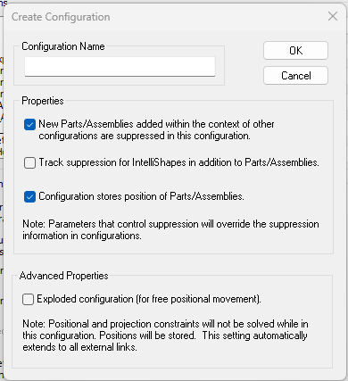
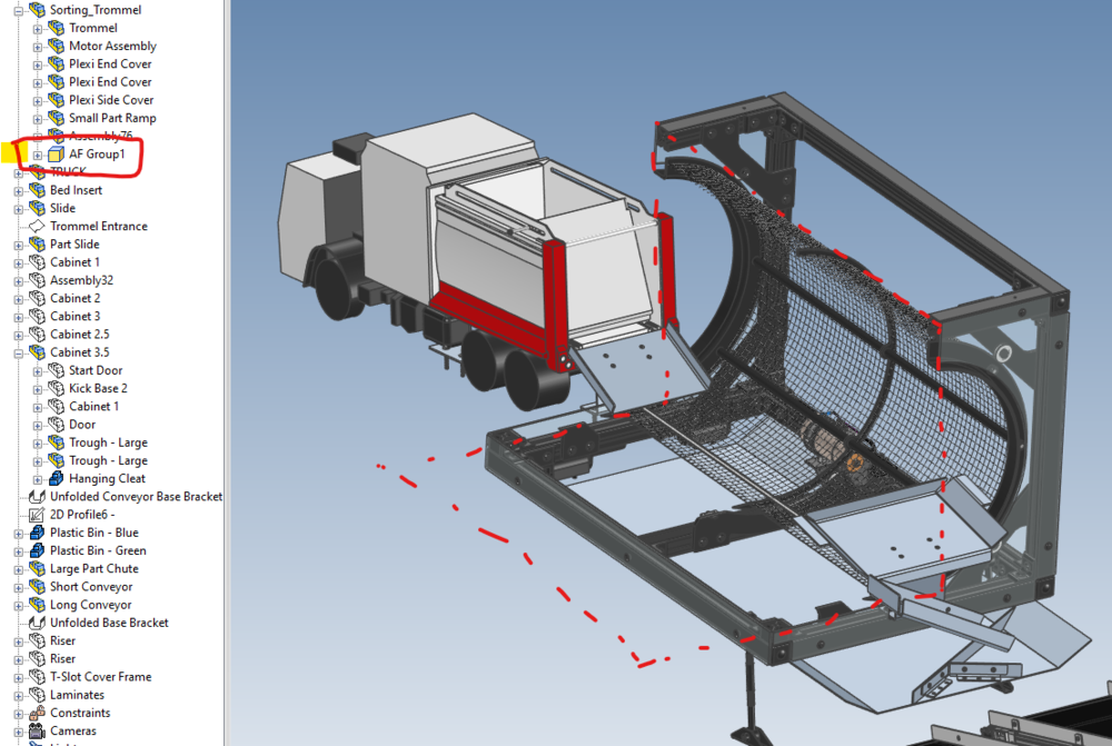
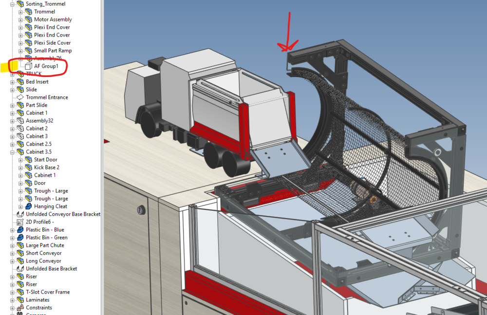
This is something I've never messed around with but I feel like it will be very helpful. The way we typically create configurations so that they don't affect the other configs we've created (when doing sub assembly and exploded views for instructions) we select the top and bottom (of the top section). I'm noticing that when I dropped a hole block on an assembly and it created the assembly feature that even though the AF is suppressed in my other configurations, it is still showing on screen and in drawing views. It is vice versa as well, if I hide it in another configuration then it shows as unsuppressed in my scene browser but isn't visible in the scene unless I select and unsuppress again. Do you know if this is just due to the configuration options selected and if there's one that should or should not be used? - Configuration options selected: Configuration with AF active: Earlier configuration shown suppressed but still visible: Also, clearly you work within CAXA draft for your drawings where we typically work within the 2D drawing environment. Do you find there's more of an advantage in CAXA such as tools or speed? I worked with AutoCAD in high school and college (two decades ago now almost) so my flow of working in an environment like CAXA would be slow to learn tools, commands, setting up views, etc. but if it's better in the long run then I'd be willing to put more time into it. Thank you, -Logan
-
Editing 2D Viewport - Quick View Quality Cuts Off Image
LSMITH replied to LSMITH's topic in General Discussion
Thanks Cary, I do remember the shift when going from non-shaded to shaded views in older versions but never used the perspective view much. I appreciate you submitting it into R&D. -
Editing 2D Viewport - Quick View Quality Cuts Off Image
LSMITH replied to LSMITH's topic in General Discussion
Thanks Cary, a OneDrive link to download the ICS and ICD have been emailed to the support address. -
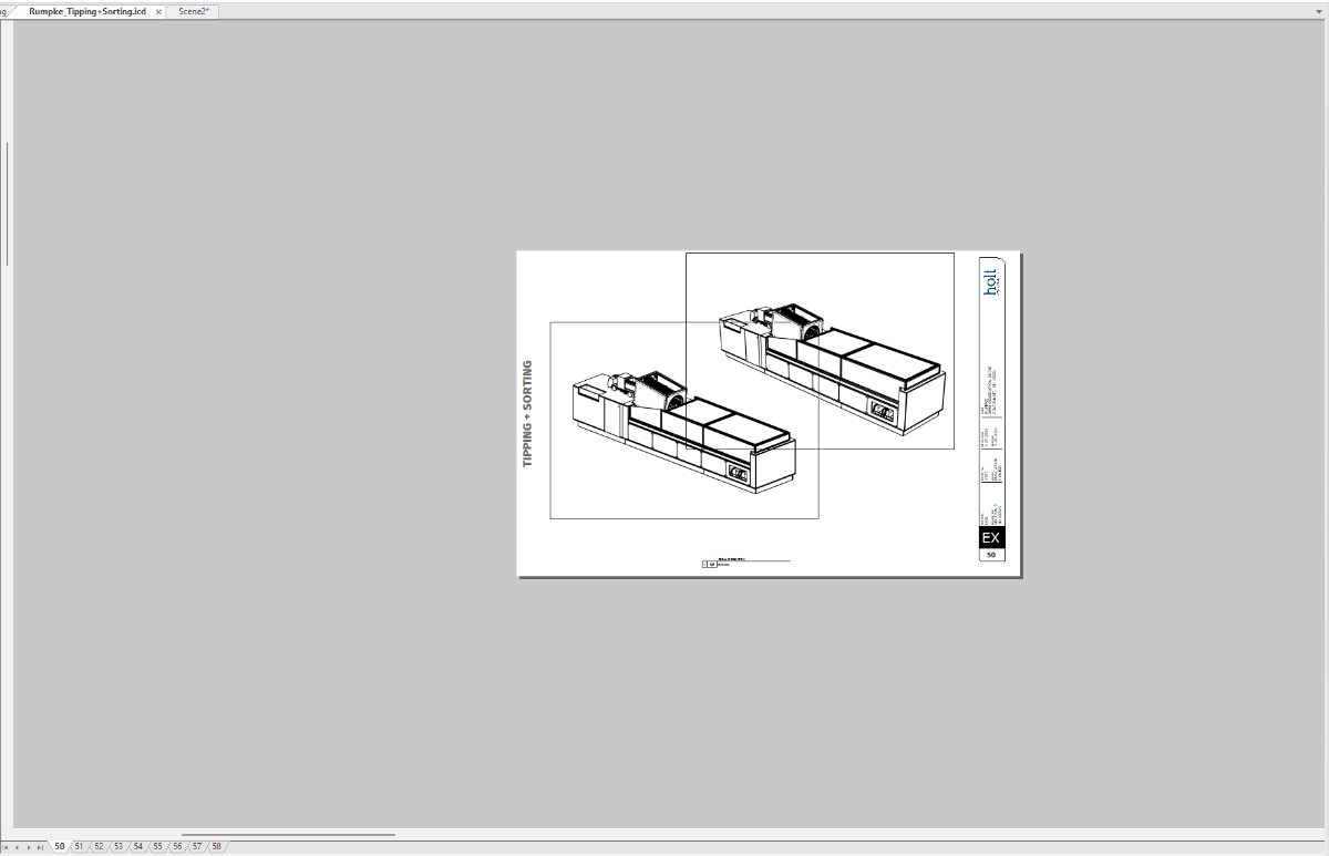
Hello, I remember this being an issue in older versions of IC but it never really affected me much. I'm working on a project where the model is very detailed and when placing views with the Draft view setting it takes a while to populate but if I place with the Quick view settings then it's, well, quick. The problem is when I change it from Draft to Quick or place it with Quick as default, the view shifts or get's placed with part of the scene cutoff outside of the viewport. It seems to only be affected when placing a view in perspective. I like to place at 45 degrees rotated horizontally and 22.5 degrees rotated vertically. It also is fully visible when zoomed out on the screen but when zoomed in it changes. Is there a way to either prevent this, re-center the view, or change the viewport bounding box after it's been placed? See the image references below, the frame has been added to both views to show the viewport extents. 1: This is zoomed out on the screen, both at the same scale. The only difference being the top right is in perspective. 2: Now the same screen zoomed in. You can see how the view has shifted or zoomed in somehow. Any thoughts or input would be appreciated. Thank you. -Logan

-
Copy / Link Positioning Constraints with Assemblies?
LSMITH replied to LSMITH's topic in General Discussion
Assembling everything I wanted to copy to an external file and then inserting that back into the file did work. I was able to disassemble the inserted part and keep the constraints. I'm hoping there's a faster way to do this as now the individual parts are no longer linked with the originals. -
Hi all, I've searched around and haven't found anything directly related to this but it's a question about copying or linking parts or assemblies that have positioning constraints. I'm building a platform that has gas shocks to assist in raising it. I've modeled one end (two posts with connecting beam, attachment points, and shocks consisting of a body assembly and a rod assembly. I'm successful in setting all of the constraints to act as I would like for this end. The opposite end of this structure is exactly the same. I can copy or link everything I've built to the other end but it doesn't bring the constraints with them. I imagine this is more than likely a setting that I'm missing but I was wondering if there is a way to bring these constraints over with the copied or linked assemblies. I would like to avoid having to reset all of my concentric and distance constraints on each shock. Would saving the assembly as an external link and then placing that external link back into the model bring with it the constraints? I could then unlink it from external, add the assemblies together however they needed to be. Thanks for any input you may have. Trailer_Movement_2.mp4
-
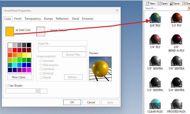
Hey Kevin, I know this tip is 2 years old but I did just learn you could rearrange the items by shift+dragging so that's nice. I wanted to know if there was a way to regenerate the item thumbnail after it has been added to a catalog if you were to go in and edit that item. Often I'll go in and make changes to smartpaint properties and wanted to know if they could be updated without having to drag them out of the catalog, edit, and drag back in. I'm trying to make changes to a material label catalog of smart paints someone else created and want to update the preview thumbnail.