snelson
-
Posts
471 -
Joined
-
Last visited
Content Type
Profiles
Forums
Blogs
Downloads
Articles
Gallery
Everything posted by snelson
-
I get the same thing too, randomly, and definately choosing an assembly and not just multiple indvidual parts. I'll email an example scene of 2 assemblies that do this every time it gets put into them catalog.
-
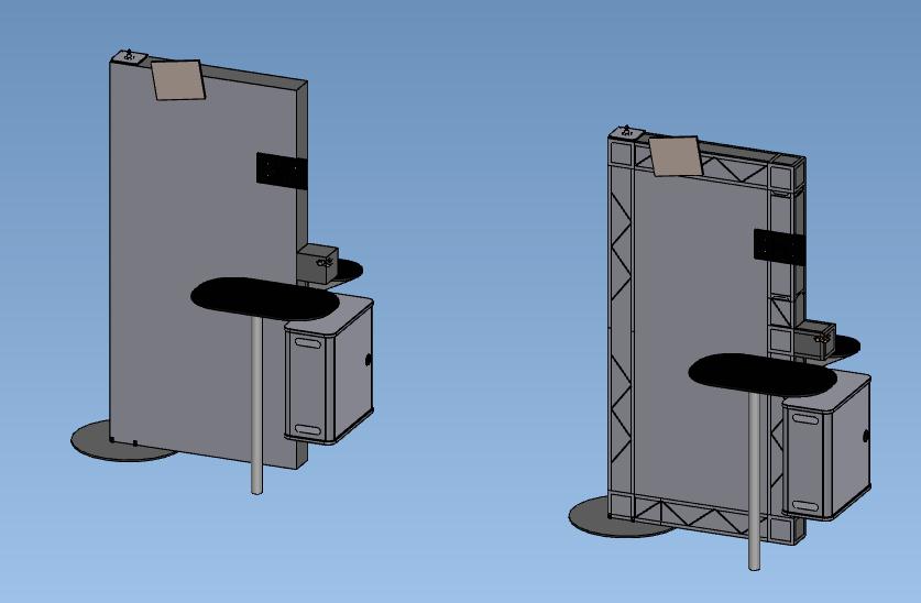
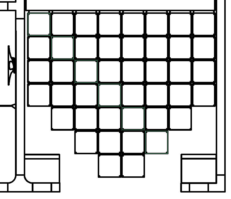
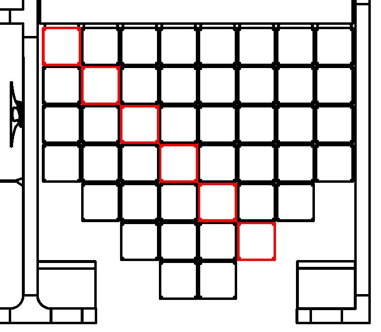
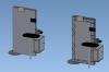
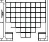
We've had the same issue for years. There are some old posts about this that I can't find right now with other work arounds but no solution. Seems best to just suppress the internal parts altogether for the screenshot, if you can. In the image below, the left side has the internal hardware suppressed, right side is how it always shows. These are solid, non-interfering parts.
-
What do you mean "new method" and "new option"? I'm not doing anything different then what I've done before. So, regenerating the catalog IS different then regenerating parts in the scene? We don't have time to evaluate each model when doing a regenerate of any type. No chance, no how. I have to regenerate very often just to be able to select parts in my drawing to attach a dimension to or change it's color.
-
When we upgraded to IC2014 I opened all of our catalogs, regenerated them individually and saved them. I create a new scene file, create a booth model with parts from the regenerated catalogs, select all and regenerate. It then asks me with the new pop-up if I want to update them to the latest version. I can regenerate a catalog, save it, drop in one part, regenerate the part and still get the pop-up... Shouldn't regenerating the catalogs have taken care of this already? Whats the difference between the two?
-
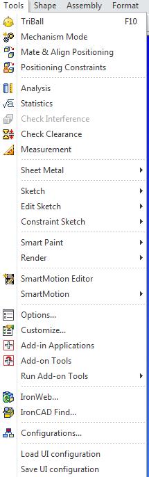
Help says to go to Tools, Operations, Ghost but there is no Operations under Tools.

-
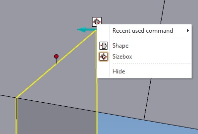
I don't know what it's called but I wouldn't mind if I never saw it again. Is there a way to shut this thing off for good without hiding it each time on each part? It's impossible to drag a handle with this thing always covering it up when dealing with a small shape or a straight on view. Thanks, Steve
-
Turns out that the couple of people that were able to update found so many bugs using legacy files that we're going back to V12. Hopefully they'll be able to put up some bug reports next week. The examples were: -bringing in an assembly puts one part of the assembly in the right place and the other part detaches and goes way off in space. -when opening a scene, it says it's in the default config but it's not and the only way to fix it is to switch back and forth within the configs. -Ctrl+Drag to replace an assembly with an identical assembly makes the new one lose all part properties, sets Qty to 0 and sets it to Expand. Hopefully they can shed more light on those next week though.
-
This was all done by Michael on around 11/26 so I have no clue. Sounds like it since I'm running the Setup.exe file and not a Download.exe. It's worked for 4 others so far. I'll just talk to him Monday when he gets back.
-
Thats how this was done, running the setup.exe.
-
It restarted 2 computers here while installing this morning. The 2nd install attempt for the other guy worked fine. The build appears to be 11090 on the other PC that worked. It's a web download. I'm only getting 10kb/sec download and don't want to isntall a download helper without talkin to our IS dept and Mike's not here today to help troubleshoot.
-
I've got 202gb free disc space. During the 1st install attempt it restarted the PC at what seemed about the half way point of the install, no warning. Since the shortcuts were on the desktop I attempted to run as Admin, entered my email and code and it said my email was not in the system or something to that effect. 2nd and 3rd install attempt both gave me the "There is not enough disk space to complete the installation. The installer will Stop!" warning. Any ideas?
-
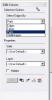
We have up to a couple hundred parts per scene and assign different colors to different parts in the same view in the same way. After you're done picking the parts you need in one color, hit Apply, then change the Style or Layer, then go back to the tree or select other parts in the view and go back and hit Apply. (not the green check mark for Apply and Exit, but the Apply button) Is that what you were lookin for? PS, you can also select parts and right click on a part in the view that you've selected then choose Set Curve Properties instead of going back to hit Apply.
-
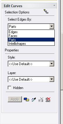
We do this on all of our instructions drawings. While in 'Edit View Curves', change the 'Select Edges By:' to 'Parts' then pick the parts individually without holding any keys then hit 'Apply'. Just know that if you click a bunch of parts, then accidentally pick off to the side it will deselct everything and you have to start over. I just pick a few at a time, hit apply, then go back for more. Hope that helps, Steve
-
Must be some late nights, huh?
-
Selecting a solid color for the background quickly
snelson replied to mgajewski's topic in General Discussion
Using the same build version here and drag/drop color from the color catalog doesn't work for me. It did work in previous versions for us too. -
I guess this just doesn't make sense to me then. To me, all it needs to do is make an assembly anchor point the exact same as the first item you pick. I don't see where it needs to think about anything or even care about mirrioring. Just match the same anchor point orientation. Steve
-
I'm seeing this in many places now in my newer files. I wouldn't doubt if mirroring is involved in the rest of em but I'd like to see this fixed before it gets in all of our files. Granted I try not to mirror if I don't have to, a lot of our parts are simple enough shapes for it to not matter until something like this comes up. Steve
-
Renaming IronCAD Drawing Files in Explorer
snelson replied to jparrish's topic in General Discussion
Kevin, when we went through this issue in emails last september you were thinking it had to do with indexing of files on the mapped drive. It was filed under incident 96878 "file copy and rename" Wish I could recall what fixed it but hang in there Joel, this was a huge headache for us last September. It wasn't any unlocker tool though, I'm sure of that. Steve -
So this isn't the correct behavior? You had us worried...
-
We do it a bit different. We pull parts out of a catalog to make assemblies instead of the other way around. So all parts are pre-defined with an anchor point and then the triball sometimes on the anchor point, and sometimes moved for easier positioning after bringing it in to the scene. If this part is left separate, there are no problems. A few weeks ago was the first time I'd ever seen the assembly orientation different then the first part in the assembly, and it had to do with this part.
-
Eric, Which behavior did you running into thats odd? I think Cary is sayin the align to global behavior is normal.
-
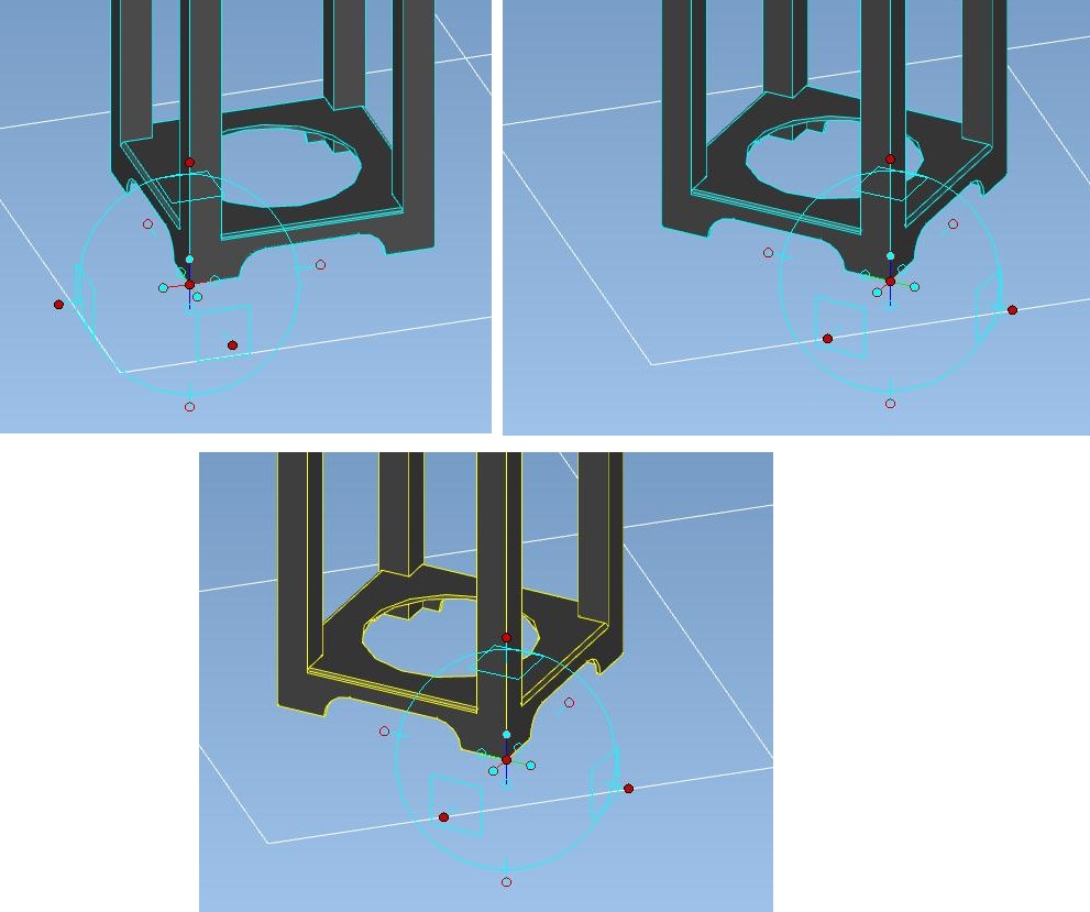
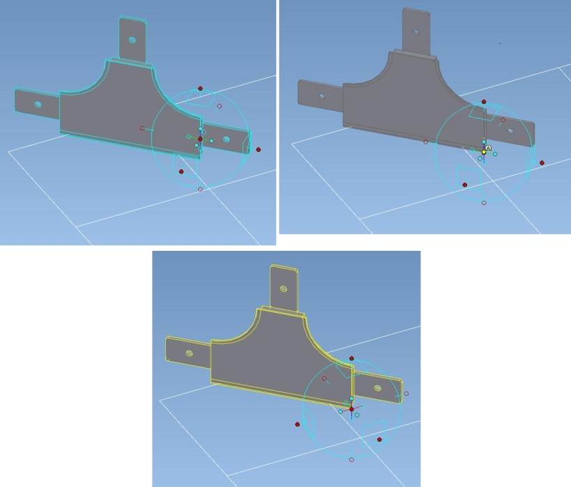
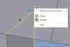
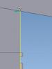
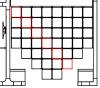
Then the better question is why do all of our other parts NOT act this way??? If i use other parts to do this, it creates an assembly anchor point where the 1st part's anchor is, where it is aiming. So if what you're saying is correct, then the picture below is the wrong behavior. The anchor point would be in line with that grid if it created one aligned to the UCS every time. Steve
-
It's being put on your FTP right now called Tbase. Guess I could have just emailed it too...
-
It's in all scenes. All anchor points having to do with the part/intellishapes are in-line with the the edges of the part yet when it's assembled as the 1st item in any assembly, in any orientation, it changes to match global. The assembly anchor is what changes, it wasn't pulled out of an assembly though before this. I'll have it put on your FTP today Cary, thanks. Steve
-
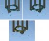
I have a part that has it's anchor point set in line with the part yet any time I assemble it with something, or even just itself for testing purposes, the triball orientation changes to match the global UCS. What would cause this? Or is it a bug? Let me know if you need any more details. Steve