

Attachment Points

Entry posted by BSTAFF
1,423 views
Attachment Points are used to join parts at specific locations when dropped out of catalogs. These points can also include constraints that limit the degrees of freedom when moving those parts. This article covers a few topics; First, how to create, position, and name Attachment Points. Then, we explore the constraints that you can use to fine-tune the motion in mechanism mode.
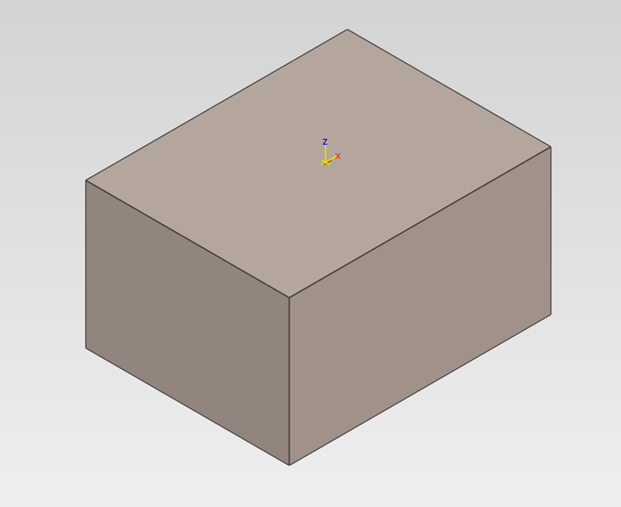
Creating Attachment Points is simple and can be done in a couple of ways. The first way is to use our Attachment Point tool within the Tools Ribbon bar. (Note that you can place Attachment Points on the feature and part level, so pay attention to which drill down you are on) The second way of creating an Attachment Point is to activate the TriBall on the part/feature, right-click, and select Create Attachment Point based on TriBall Location. After placing the point, you can move the Attachment Point by clicking the point until it glows yellow, then activating the TriBall. You can now move the Attachment Point to any location you choose. Keep track of the Axis directions when moving the Attachment Point, as this is important for when you constrain it.
Now that we have an Attachment Point created, we can constrain it. Right-click the Attachment Point and select “Set Name.”
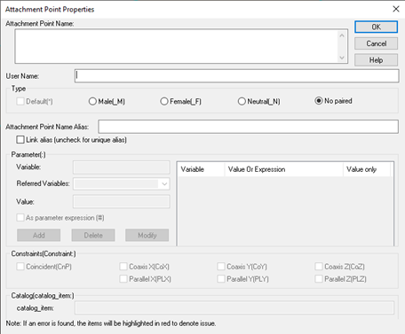
You should see this screen.
Set an Attachment Point name to tell IronCAD which Attachment Points you want this point to connect with using the Attachment Point Name box. Set the Type, which determines how it interacts with points of the same name. Finally, we can set the constraints, which limits the degrees of freedom our point has to move in the scene.
- CnP: This is the Coincident constraint; it stops all Translation for the parts attached while allowing the part to rotate freely.
- CoAxis: This constraint ensures that the selected axis is coincident with the corresponding axis. Example: CoX: ensures that the X-axis is always coincident with the other X-axis, this prohibits Translation in the Y, and Z direction, but allowing rotation about the X-axis.
- PL: This is the Parallel constraint, this constraint does not limit Translation at all, but it ensures that the selected Axis’ are parallel to each other. Example: PLX allows Translation in the X, Y, and Z direction, but only allows rotation about the X-axis.
You can connect your Attachment Points by dragging the part into the catalog, dropping it onto a part that has an Attachment Point with the same name. Attachment Points can be also be paired by using our Attachment Point Connector Tool in the Tools Ribbon.
Additional tips:
- Attachment Points often overlap with other Attachment Points on a part, so it difficult to select the correct point when hovering over a cluster. You can select the one you want by using the Ctrl-Alt- Left-click shortcut to see a menu of all the points you are hovering over.
-
Attachment Points work well with the IronCAD TriBall, allowing you to easily create copies and links to other Attachment Points in a part.
- You can even create attachment points with the TriBall. Deactivate the TriBall and move it to the desired locations. Right-click on the TriBall and select Create Attachment Points.
- Also when you have multiple attachment points on a shape, Turn the TriBall on and Hit Tab to toggle through the attachment point locations. This is a useful way to setup locations for Translation and Rotations on parts without having to manually reposition the TriBall each time.
-
Attachment Points can be saved in a catalog, allowing you to drop them on the parts you want also want to constrain. Simply Drag and Drop them into the catalog for reuse.
0 Comments
Recommended Comments
There are no comments to display.