


arfa
-
Posts
28 -
Joined
-
Last visited
Content Type
Profiles
Forums
Blogs
Downloads
Articles
Gallery
Posts posted by arfa
-
-
Any updates on this method ?
-
4 hours ago, Cary OConnor said:
I took a look at the file. Currently, the animation will not fully handle all constraints. Constraints can sometime break the animation in other words. In your case, I think it is the second animation (on the wrist). It you remove that animation, it will function for the first part. For this animation, if we understand the end goal, we can help suggest how to get it to resolve the correct animation (without the constraints or with just a few and using assemblies to group objects). For example, if you remove all the constraints, you could make an assembly of all the arms. Then constrain that assembly to the spinning base. Then group the wrist and clamp at the end as an assembly and apply a spin on that assembly.
Hi @Cary OConnor ,
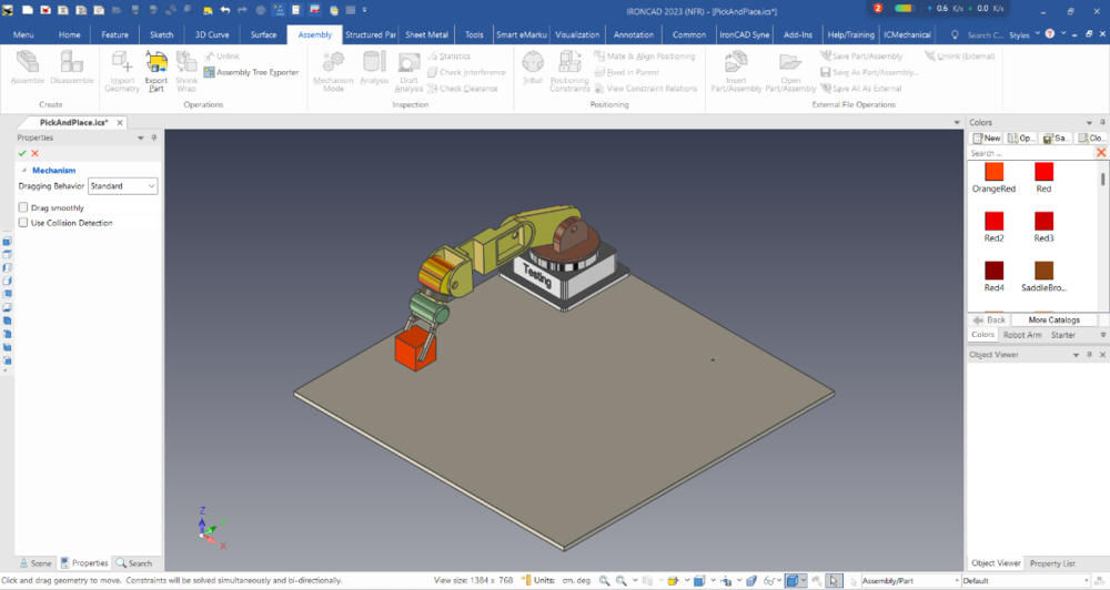
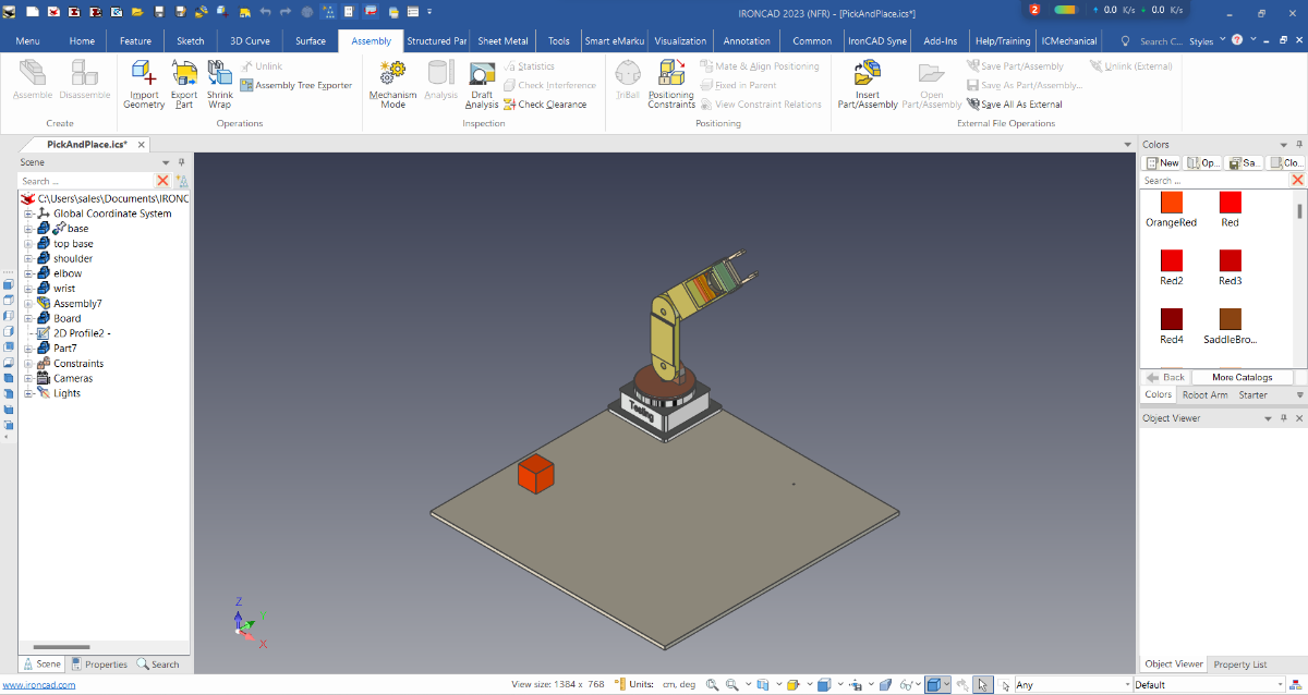
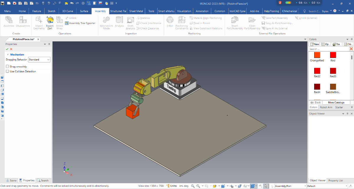
My goal is to simulate this robot moving to take a orange part from one point and bring it to another point,
In other words it is using the concept of "pick and place".

* The picture below is an example to show how the robot takes it using mechanism mode
I will try to understand the example you gave,
By the way, can you give the best way to do this kind of simulation?
Thank you.
-
-
 1
1
-
-
9 hours ago, Cary OConnor said:
Seems like this may be fixed with some of our latest DLL's. We will be releasing a SP1 shortly. Also your smart assembly will need some constraint last part for alignment between that fork. Otherwise it will float.
Thanks for the advice @Cary OConnor
-
15 hours ago, Bertrand Kim said:
Hg armfa,
Turn off [Rotation About Anchor] in the Motion's property, and make some constraints to follow the rotating.
And I'm guessing for some reasons something is weird with your file.
robotanimation2.ics 1.48 MB · 0 downloads
Kfm
Hello Kim ,
Thank you for giving me a useful solution and it worked after I followed your method.
But when I add another new animation, the other part does not follow the first animation even though I have done some constraints(parallel). -
Hello Ironcad Community,
I have a little problem that when I turn on smartmotion, the alignment on my part is a bit confused.
And when I run the simulation to my top base only, some parts follow and some don't.
And after I delete all the constraints, the result remains the same, do I need to change the correct anchor position each parts maybe?
Anyone here who knows how to operate smartmotion please guide me the right way.
Thank you ,
-
On 6/27/2023 at 8:29 PM, aalbè said:
I think it is Group AF1,
contains an Hcylinder that drills part1if you delete it, the animation becomes smooth again
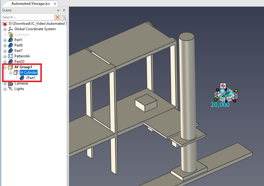
Hello @aalbè
Ouh yes, what you said is true , it becomes smooth after i deleted it,
Thank you so much for helping me solve it.
-
 1
1
-
-
On 6/28/2023 at 2:38 AM, SSIMMONS said:
Are you looking to do something like this? Like Cary said, if you simply want to make a solid into a mesh, just export to one of those file types.
Thank you @SSIMMONS for providing another solution that may help others in the future.
I will use the method given by Cary for now.
-
On 6/27/2023 at 10:01 PM, Cary OConnor said:
Yes when you export to STL, OBJ, VRML for example, those will create a triangulated mesh. We don't have much in the way of editing tools for that type of geometry and their may be other editors for that purpose.
Understood and thank you @Cary OConnor
-
Hello Ironcad Community ,
why does my smart motion editor become not smooth when the three selected parts move together? is there any way to fix it?
-
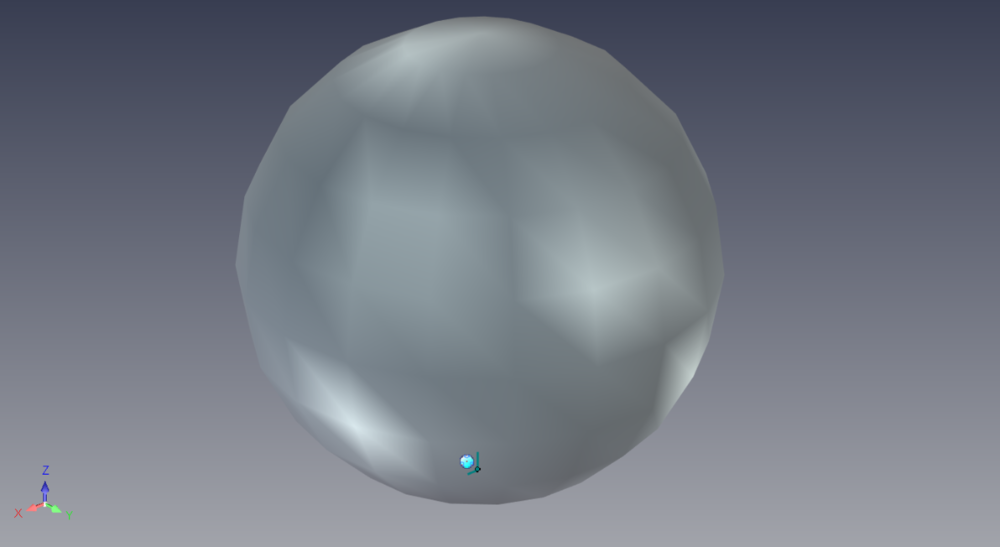
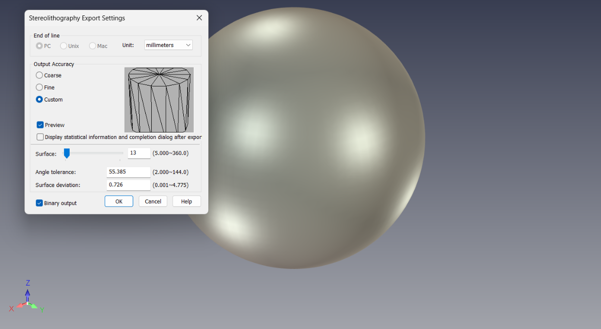
I have tried to export the file to stl format and make some adjustments .

And this is the result, is this the right way?
-
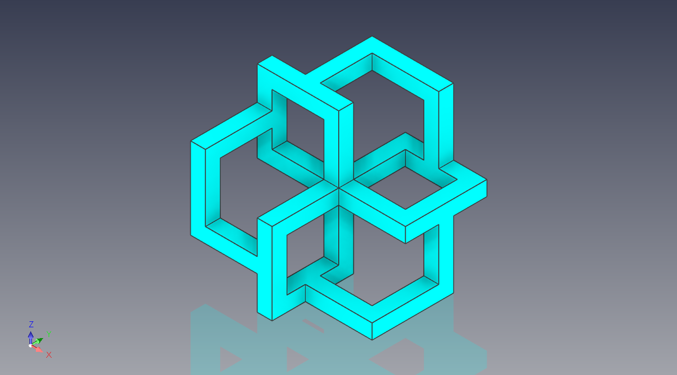
Hello Ironcad Community ,
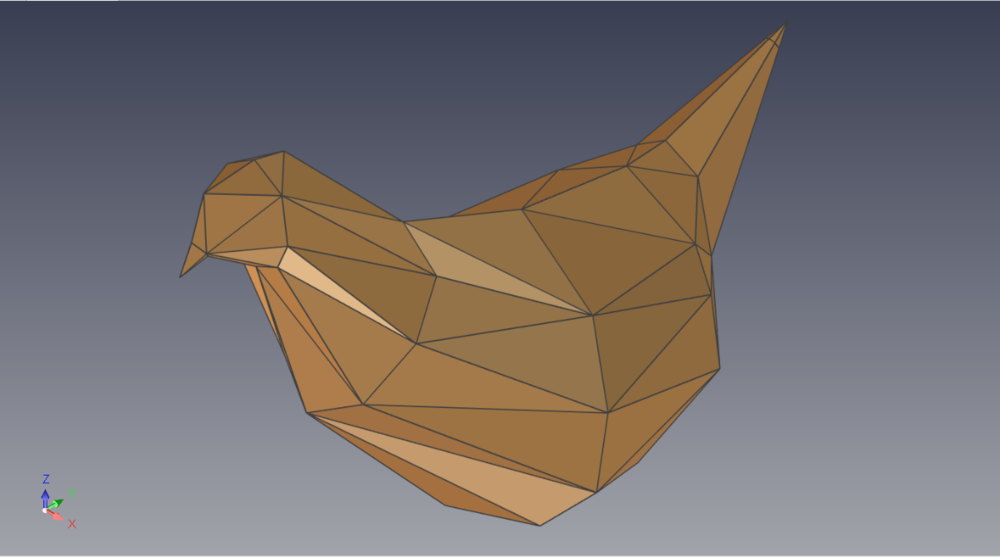
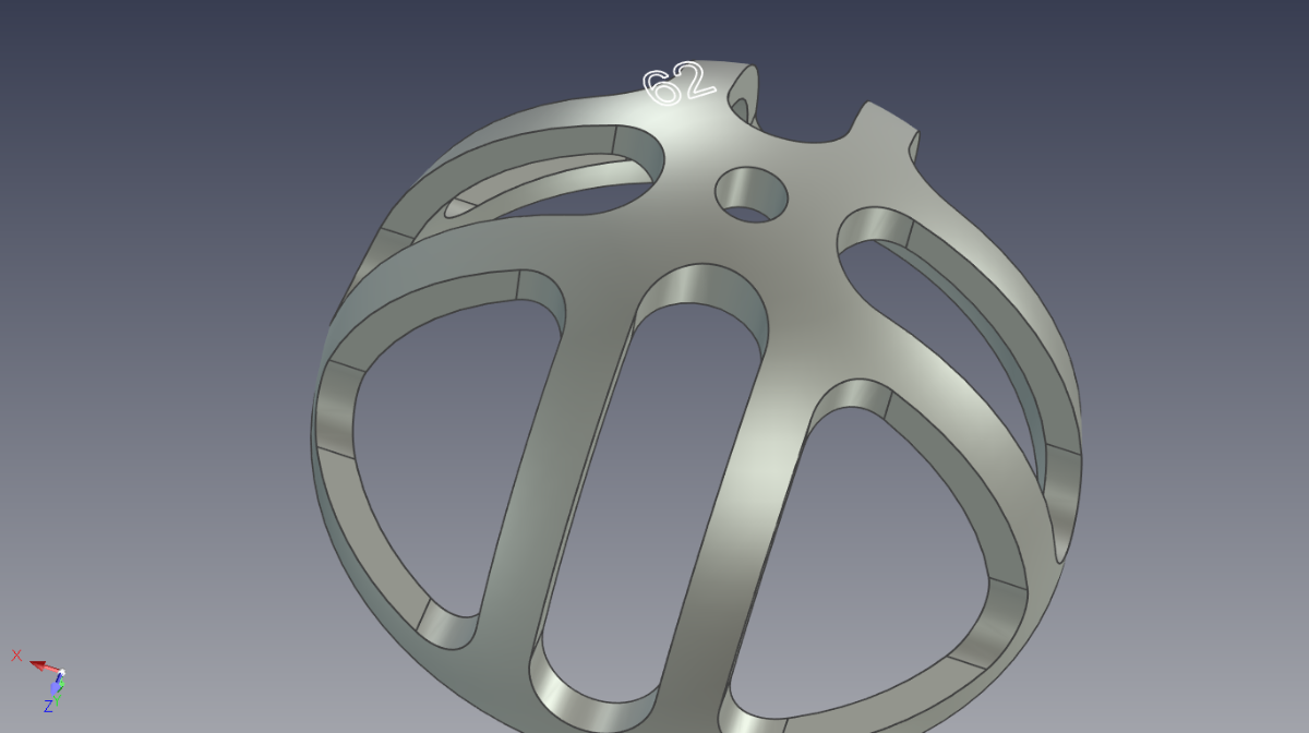
Can ironcad convert from solid/smooth part to polygon/mesh shape ?
*I have attached the picture below as an example of the polygon shape that I have downloaded from grabcad
Thankyou.
-
-
19 hours ago, Bertrand Kim said:
Hi Arfa, you can use parameter
SAMPLE.ics 148 kB · 4 downloads
You can create the same animation. But I'm not sure IC could make camera movement
Kim
I really appreciate it, thank you so much Kim !
and another thing, can the animation be made using smart motion available in ironcad or a third party application/catalog ?
-
and another question asked by my prospective, is ironcad able to make simulation the movement of the machine as in the video I inserted below by using the smartmotion function?
this video from youtube channel = Visual Components
-
Hello Ironcad Community,
can I copy/link or linear pattern part using the triball function by giving point to point distance or other related methods without caring about the distance from features to features as long as I can give how many parts I want in that distance?
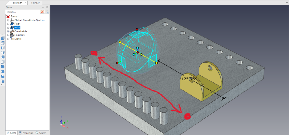
I mean, can I make it like an edge pattern that has evenly spaced by just entering how many copies we want? But if we use the edge pattern, we can't choose different feature parts, right?
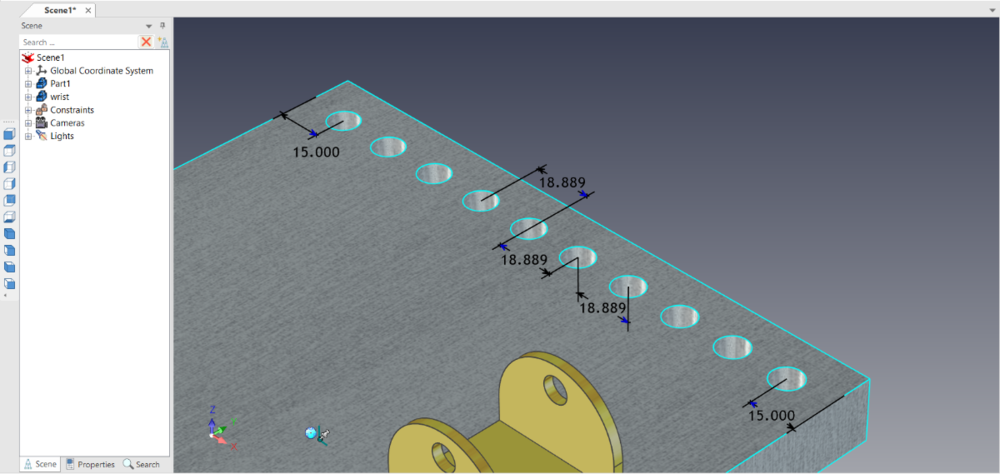
*the picture above I use edge pattern , count=10 , offset start and end = 15
This question was asked by my prospective, forgive me if my English is not satisfactory because I use google translate, hehe thank you...
-
On 6/4/2021 at 8:20 AM, Cary OConnor said:
Well you can possibly use the Emboss tool and set the depth to something small (.1 or less). However, you have to create individual curve sets. Basically select on each face of the logo and create a 3D Curve. Then run the tool for each set picking the correct faces to project and directions. It is not exactly a wrap but more of a projection. It may work out for you however.

Hello Cary,
can you make video on how to do like you did ? I am not clear with the explanation given
-
8 hours ago, IronKevin said:
Correct, the wrap only supports cylinders.
Noted with thanks ,
Is there any solution to place text on this surface?
-
Hello ironcad community,
how to use feature wrap emboss on this face ? is it possible to do that ? because it will come out a box that says only can do for cylinder face

-
14 hours ago, Bertrand Kim said:
Yes, I also lost my picture when I followed your method.
Try to save the template with "Save As" tool instead "Save as Template for Catalog"
I'm sure tew new tool "Save as Template for Catalog" that is deliveried with IronCAD2023 makes lost a picture.
Kim
Thank you so much , its worked
-
1 hour ago, Bertrand Kim said:
Hi arfa,
Hm... a picture with template is working at here, can you record your screen with process?
Kim
Hi @Bertrand Kim,
sorry that my laptop has a little problem to record the screen but I will explain how I do it
1. I modified the sheet by placing a picture
2. then I save it as a template for catalogs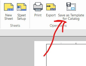
3. then I move the file in the template file just like the file that is directed in the directories
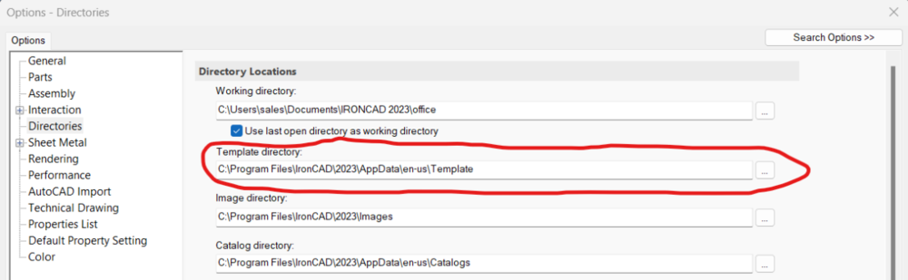
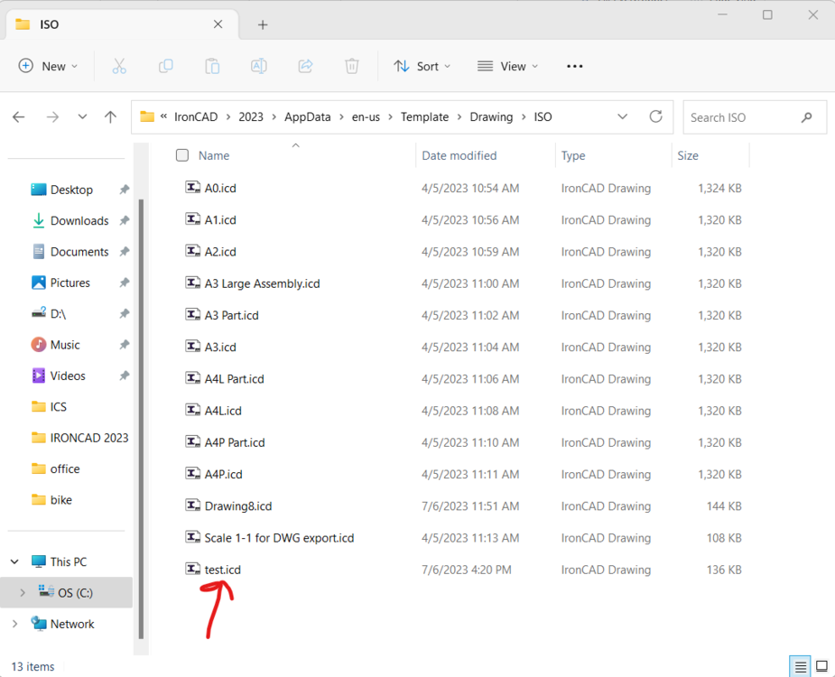
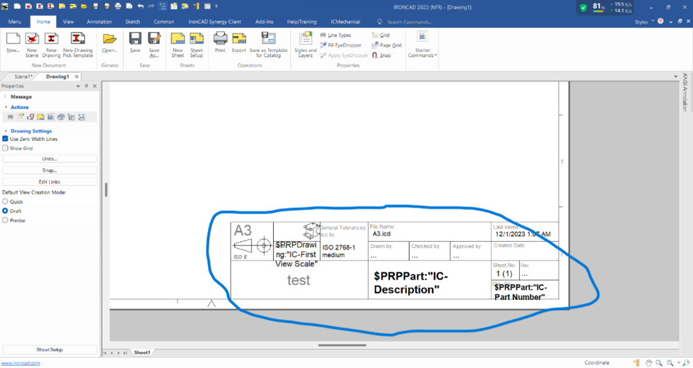
4. then I made a new drawing using the template I had saved a while ago and what I got was no picture in the drawing
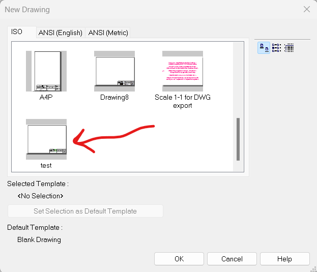
is my way correct? forgive me if you are still not clear
-
Sorry @IronKevin
I have saved as a template with a picture, but when I use the template on a new drawing, the picture is missing, may I know why? is the picture not allowed to be saved as a template?
-
Thank you so much ironKevin ,
it is very helpful.
-
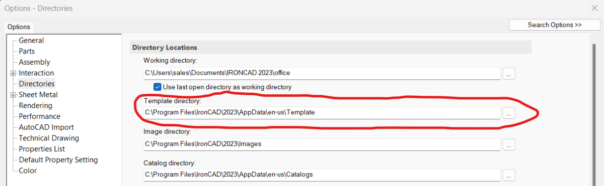
Hello ironcad community,
1.Can i put an image or company logo on this table drawing ?
2.Can i set as default drawing template that i modified?Thank you and Forgive me if my English is not good.


Loss of Expression in the Parameter box
in General Discussion
Posted
Hello IronCad Community,
I have a little problem where when I drag the top cover from the catalog, I find that I lose the expression in the parameter box for that part, is it because my expression is wrong?
* Fyi , X put at X axis , Y put at Y Axis , and for the Top Cover please drag to the Y Pallet.
For the Pallet base Handle , Length put value 1150 + (always 1050 ) to make it better and for the Width put value 1100 + ( 500 )
* The file below is a catalog file
Pallet.icc
That's all, thank you.