tgjang
-
Posts
447 -
Joined
-
Last visited
Content Type
Profiles
Forums
Blogs
Downloads
Articles
Gallery
Everything posted by tgjang
-
Thank you very much Cary.
-
In order for users to test IronCAD 2024, they need to install and use IronCAD 2024 on their computer. However, IC Beta testing is very limited as IC 2024 data is not backwards compatible with IC 2023. Also, there is no mention of the CAXA upgrade, which I think users are interested in. In my opinion, a lot of testing should be done before the IronCAD 2024 version is released to minimize problems when it is released. Thanks
-
Hi Changes to Surface when holes are hung in a solid file. Therefore, if you change the kernel of the current part from Parasolid to ACIS kernel, it is represented as Solid.
-
When I project a CAXA 2D Drawing View from IronCAD 3D and then change the design, the 2D CAXA Drawing loses the Attach reference for most dimensions as shown in the attached video. The biggest advantage of IronCAD is that when the 3D design is changed, the 2D drawing changes with it (I know this is not possible in the Inventor so far). I would be very grateful if you could tell me what I can do to ensure that each dimension in the 2D Model does not lose the Attach reference of the projected Edge Line. (Very important issue) Thanks DIM_ATTACH.mp4
-
Hi Malcolm Thank you very much for your very valuable material. I see that you used IronCAD and CAXA as if they were dedicated programs for architectural design. I thought I had to use Ravit or AutoCAD third party program for architecture, but it looks like IronCAD works too. I see that IronCAD can be used for architectural design. Thank you.
-
I thought the most complex and largest example of IronCAD 3D modeling was a spherical gas turbine. Using IronCAD to 3D design a building from CAXA to drawings is amazing. I've asked Bing Chart and Open AI Chat a few times which software is best for FA and PLANT design, IronCAD or Inventor or SolidWorks, and without fail they recommend Inventor and SolidWorks. In my opinion, IronCAD is not bad either, but...
-
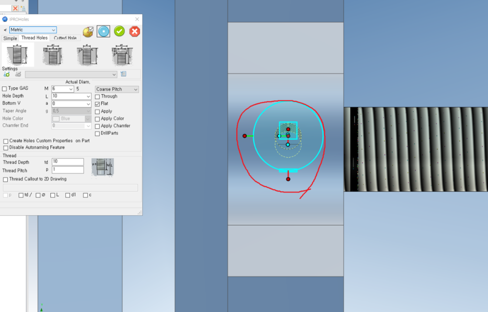
Thank you for your response. Cary. The above problems have been solved. I have two more questions 1. is it possible to use smart dimensions for Features in Structured Part, as it would be very convenient to use Lock, UnLock dimensions. 2. When I drag the Fasteners Assy catalog in ICM Mech into the Structured part and create a Bolt, it does not drill holes in the part, is this a problem that cannot be solved? In SolidWorks, when the designer bolts it, it creates a hole just like the Innovate Part in IronCAD. Thanks.
-
Hi. I tried creating a simple Vice using a Structured Part in IronCAD, but it doesn't drill holes accurately or move through round walls. I would be very grateful if you could tell me what to do. Thanks. VICE.ics STRUCTURED_PART_MODELING.mp4
-
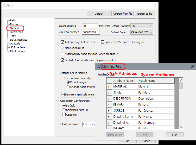
Layer, Color, Text, etc. defined by the Matching Rule in CAXA Draft Options and other drawing parameters in Parameters, BOM Table, Style Manager are also stored in the Draft Template (TemplateName.tpl) for easy use. Malcolm has created documentation and videos in the community on what you need to know. 2D_ATTRIBUTES.mp4
- 1 reply
-
- 1
-

-
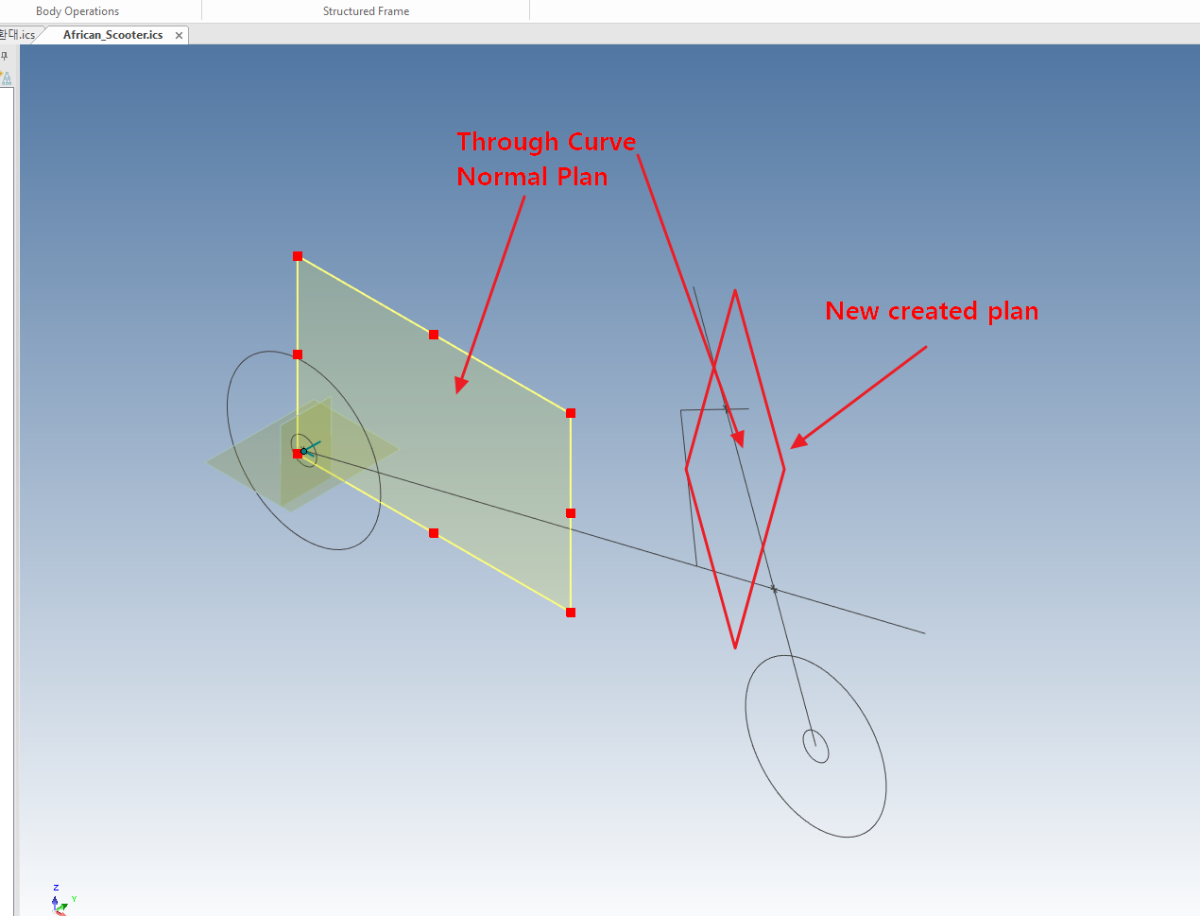
Hi I would like to create a simple sample video as an educational resource on structured modeling. I decided that the simplest African scooter will do, so I start designing it, but I get stuck on creating a datum plan and ask a question. I'm asking because I can create Through Curve and Normal Plan (Angle) very easily in Creo or SolidWorks, but I can't do it in IronCad. Thanks African Made SCOOTER-1.mp4 African_Scooter.ics

-
Thank you for answering my question. Cary
-
I want to constrain the end of a vertical Curve to the end of a triangular Curve, but when I change the size of the circle above, the endpoint of the vertical line does not follow the endpoint of the triangle. How can I make it constrained? Thanks. 3D_Curve_Constraint.ics
-

CAXA - Referencing the Last Point (when creating 2D geometry)
tgjang replied to Malcolm Crowe's topic in Tips and Tricks
Malcolm. Thank you for your quick response to my question. I think you are doing a great job using IronCAD and CAXA for a variety of structures, buildings, and machines. I really appreciate the fact that you take the time to share useful tips that are not found on the internet or in the CAXA manuals. Thank you very much. -
CAXA - Referencing the Last Point (when creating 2D geometry)
tgjang replied to Malcolm Crowe's topic in Tips and Tricks
Hi Malcolm, thanks for another great video. It looks like the CAXA you are using is linked to IronCAD in a separate window, is that correct? I think it would be very convenient to be able to work on your drawings in a separate window from IronCAD with CAXA connected. That is, when I'm working on a drawing, I often find that the dimensions are not modeled in 0.5 or 1 mm, so it's very convenient to go to the 3D scene, modify the model, and then go back and forth to the drawing. Also, I'd appreciate it if you could tell me where to specify the "SECTION" note in SECTION A-A. Thank you very much. -
Hi. maurizio. I'm very happy to hear that it was a disappointing function. Looking at your programs, I can see that you have developed it very well in a user-friendly way. As I've seen the community join, Malcolm has a lot of experience and skills in various 3D CADs and industries, so if I get his advice, IronProXT will have very good features, which will be very helpful for software sales. Thanks. maurizio.
-
Hi. Malcolm Your video and comment were very helpful to me. Thank you very much.
-
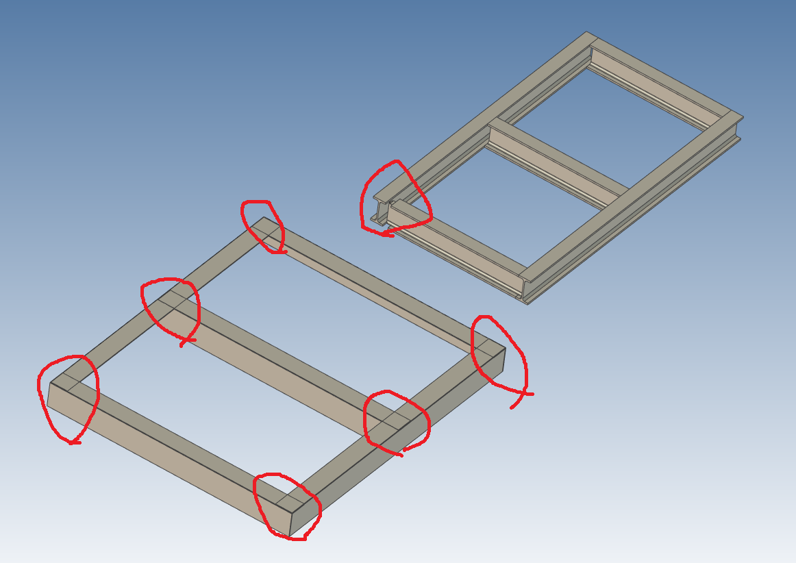
Hi 1. There are A Assembly and B Assembly in the attached file, but the part in A Assembly does not end cut like the part in B Assembly. What should I do? 2. In the case of B Assembly, what should I do to prevent this phenomenon in which the length of the part is short and trim? Thanks. EndCut.ics

-
Hi I would like to use the Bulk Drawing creation feature to create a large number of drawings at once. This is not a problem when the number of parts is small, but when I create dozens of drawings, a pop-up window appears and I have to keep pressing the Yes or No button. Is it possible to create a batch of drawings without the pop up dialog and without pressing the yes or no button? Thanks yes_no_Dialog.mp4 Ug_Belt_Roller.ics 100000-0007 BUSHING.ics A3(STD).tpl A3(STD).chd
-
Questions about Structured modeling with Skeleton
tgjang replied to tgjang's topic in General Discussion
Hi I have never used Structured Modeling in IronCAD because it is very unfamiliar and uncomfortable, and I have not found any reference material, especially about the connection between Mechanism and Skeleton, but I am very grateful that Malcolm has created and uploaded a very good material this time. I am very grateful that Malcolm has spent a lot of time creating this material without any compensation. Thank you much. Malcolm. -
Questions about Structured modeling with Skeleton
tgjang replied to tgjang's topic in General Discussion
Thank you very^100 much. Malcolm. -
Questions about Structured modeling with Skeleton
tgjang replied to tgjang's topic in General Discussion
Two more things I would like to know are 1. to verify that what I designed with the Multi Body method works and is driven by mouse move. 2. if the user sets the view direction of the oblique assembled part used to design with the Multi Body modeling technique in the 3D scene in 3D, and then creates a 2D drawing, will the 2D Drawing View Direction be disturbed when the drawn part changes direction in the 3D scene? Thanks. -
Questions about Structured modeling with Skeleton
tgjang replied to tgjang's topic in General Discussion
I tried to create this model using a 2D Sketch as a Skeleton, but I don't know if this is the right way to do it. I didn't find any tutorials or samples of IronCAD's Structured Desingn on the Internet except for Malcolm's, so I thought that IronCAD Structured Design was completely useless, but I was very excited to hear that Malcolm applies Structured Model Design about 50% of the time. Thank you very much. Malcolm Termianl_Crimper-Skeleton-1.ics -
Questions about Structured modeling with Skeleton
tgjang replied to tgjang's topic in General Discussion
Hi Hdear. I have tried to follow all the Structure Part Design from malcolm you told me and it is a completely different problem. I think this problem is similar to the feature Multi body modeling in Solidworks. Multi body modeling is a way to design the entire product as a single part and specify the features used as a single part. I am looking for a way to implement that modeling method in IronCAD like in Solidworks, or a feature like Motion Skeleton in Creo or WAVE in NX. Thanks. -
Questions about Structured modeling with Skeleton
tgjang replied to tgjang's topic in General Discussion
I should do some more studying of what Malcolm has posted on IronCAD Academy about structured mode design in IronCAD and try my hand at layout design. I really appreciate Malcolm taking the time to answer my questions. Thank you very much. Malcolm & Hdear -
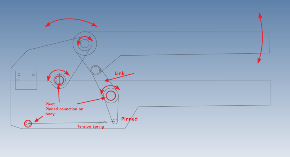
Hi I'm trying to model a Wire Contact Crimper with a method in Structured Mode, like the Creo Advanced Assembly design method, where I create a skeleton with the basic information I need to design, and the body is created with reference to that, and then I change the link lengths as I go. So far, I have only modeled in Innovate Mode and never in Structured Mode. I have tried modeling in Structured mode many times but failed because the skeleton is not fixed and the whole thing moves, so I want to know how to design in such cases. Thanks Termianl_Crimper-Skeleton.ics Design with skeletons.