JARICO
-
Posts
31 -
Joined
-
Last visited
JARICO's Achievements
")
Cylinder (3/9)
4
Reputation
-
@Cary OConnor thanks so much for your help...that did the trick!
-
Hi Cary, thanks for your response and sorry I missed it. I'll have a look a this today...
-
Hi All, Anyone have any idea what might be going on in the attachments below? For some reason when I shell the part I'm getting these weird artifacts that break through the surface, or that form very strange corners. I'm shelling before I do any blending. Shelling after the blends really limits how thick I can make the shell. I need a minimum shell thickness of 6mm. I was able to fix one of these weird corners by moving a single blend before the shell but this one eludes me. I've tried everything I can think of. If I reduce the shell thickness it goes away but that's not much good to me. Cheers, Joe

-
Thanks @Cary OConnor. I tried another other option - importing cross sections in the hope that I could do a surface loft but the Artec software only exports a 2D dxf (even though it looks 3D!) so doesn't work. It also comes into IC as a single layer so the lines are all one body. That's more of a problem on the Artec side. I could try importing 1 cross section at a time and lofting that but that's going to take a LONG time for a large part. A solid body would be easier to work with than a surface but I have a job coming up where I will be doing exactly this so thought I'd do a trial run to figure things out. It would be excellent if IronCAD had some features to make the transition from the 3D scanning world to CAD a bit easier. Even if were better integration with some of the scanning software like Artec Studio. Geomagic DesignX seems to be the tool for that job but OMG it's expensive. The Fusion 360 Slicer puggin seems like it's perfectly suited to the task I'm trying to complete once you have a reverse engineered model but I suspect it will be a struggle in 360 to work with the imported data as well. In fact there is a YouTube video on this very topic I came across that discusses all the things that should work but don't! They do find a way in the end though so that's heartening! Will keep trying! #nevergiveup
-
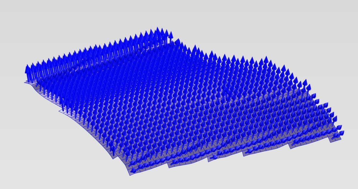
Hi Cary, Gave that a try but from what I can tell it produces the same result as when I hit Thicken and then box select the surface. I still have 1000 patches and I can't thicken in the direction I want. When I try to change direction, it doesn't work.... By the way 1000 patches is just to try and make figuring out the workflow easy. I need 10,000 to capture the detail I need...
-
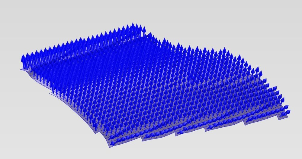
Hi @WAENGENEND, I am able to do that too however the surface is still made up of 1000 patches. I was trying to combine all those patches so it's a single surface to begin with, and then basically extend the whole surface down say 500mm with the bottom face being perfectly flat. I don't know if there's a way to extrude up to the surface which I've also tried to figure out, or to boolean it somehow to end up with the result I want. Basically I want to end up with an intellipart that I can chop up into "strips" to make a buck....
-
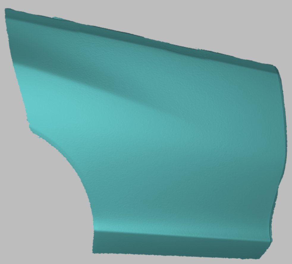
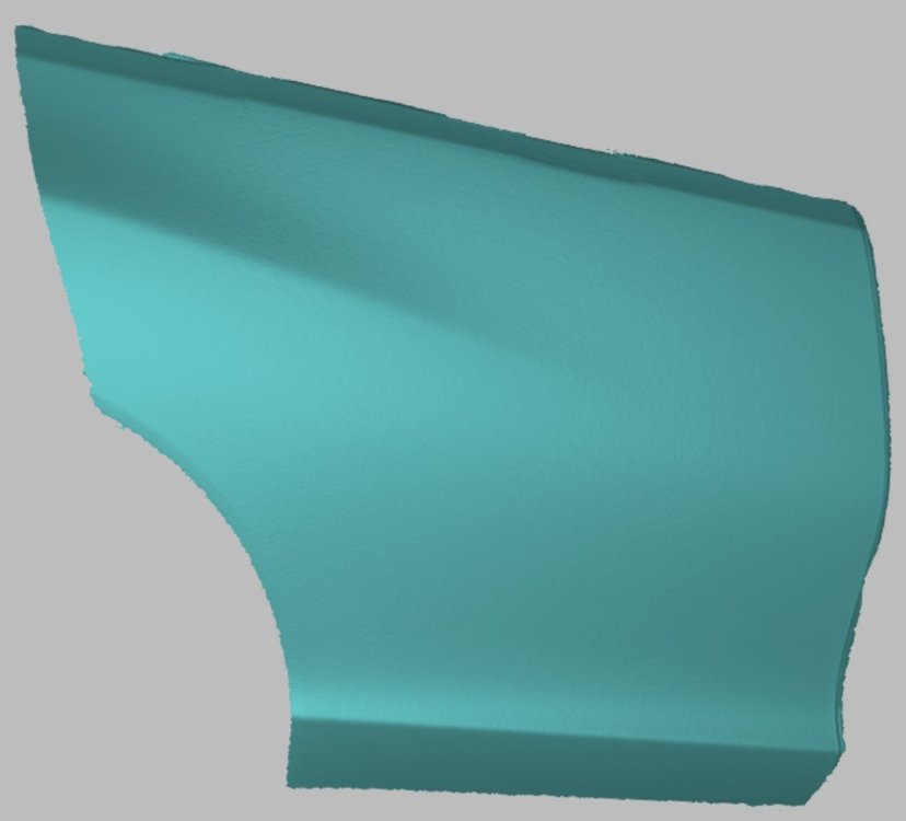
Hello, I've been trying to figure out how to work with 3D scanned surfaces in IC. I'm using an Artec Leo scanner and the latest Artec Studio 17 software. It has a surface to CAD feature that creates a surface constructed of a series of patches. You can export in Step, IGES or x_t formats. When importing into IC you can't do much with the result. I am trying to solidify the object to make a mold of sorts, although the actual part I'm using is just an experiment to see if I can figure out a workflow. It's just the rear door from my car. First thing I tried was to extract the surface. To capture the detail I used about 10,000 patches. Extracting took forever. It processes one patch at a time so 10,000 was a bit much. I dropped it down to 1000 just to test (the door skin lost features) but the resulting part from the extraction was still pretty much the same thing as the import. Just a brep made up of 1000 patches. I tried to Sew it....didn't work. I then thought that I would thicken the result and that worked but I couldn't select the direction I wanted - no matter which direction I selected it would only thicken in the one direction which was the opposite one to what I wanted. I'm attaching a few files. Just a jpg of what it looks like and the 1000 patch surface to cad file in IGES format. If anyone has any idea how to make this work I would be incredibly grateful for the advice! The result I'm trying to achieve is basically a cubic solid of sorts with the top face that matches the inside of the door skin. Maybe my approach is completely wrong and this is a lot simpler than what I'm making it... hope so! door 1000.IGES
-
Thanks @Cary OConnor! Very much appreciated. My machinist will be happy and I've learnt something as well which is always a good thing. Cheers!
-
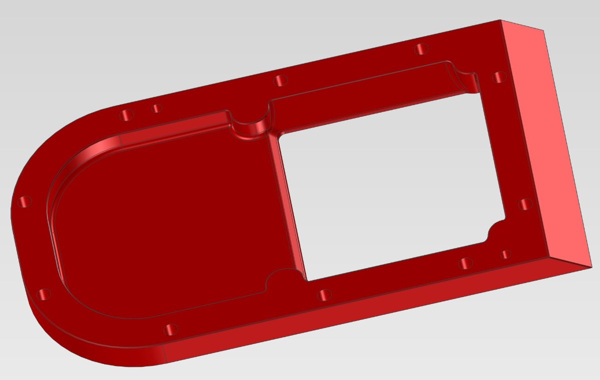
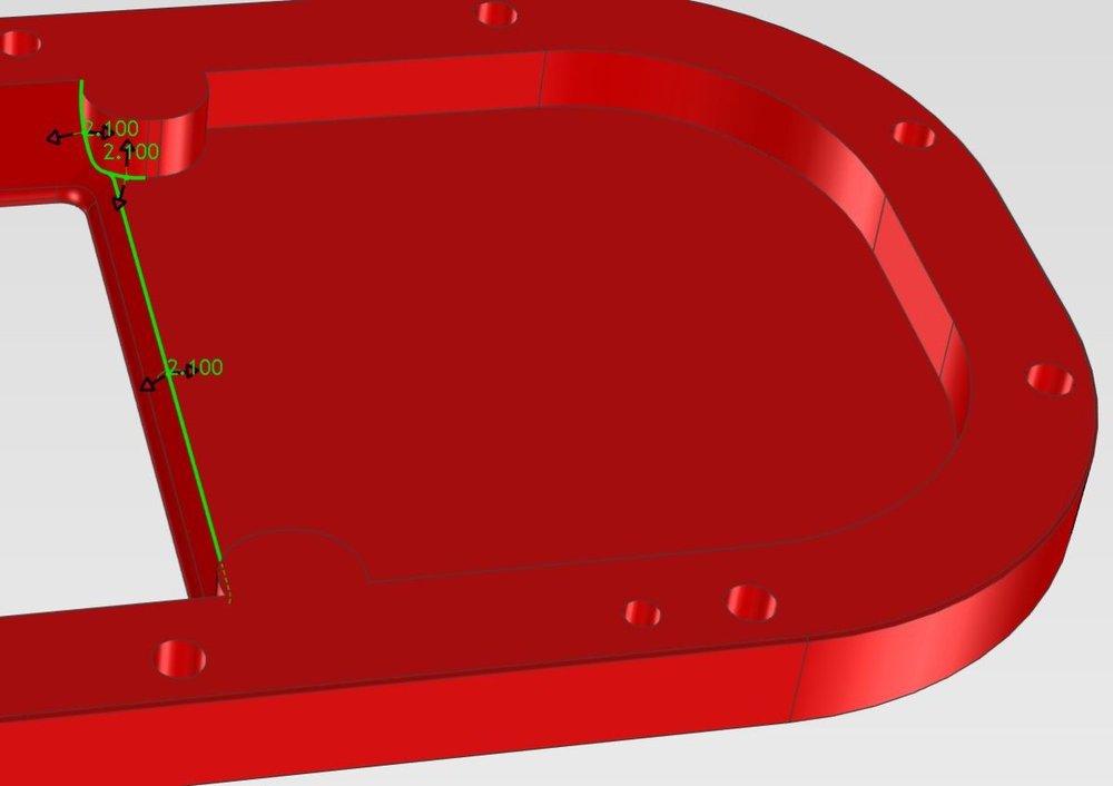
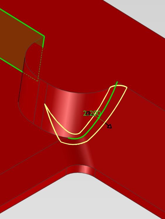
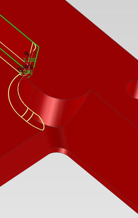
Hi @Cary OConnor, thanks so much for your help. Much appreciated! The other end is the more problematic one however. Apologies if I didn't make that clear. Screen capture below. I'm trying to blend all edges to about 3.2. I managed to get to a max of 2.1 around the bosses and the bottom face before the blending function threw the toys out of the pram. Screen capture of that and it's also in the model I attached previously

-
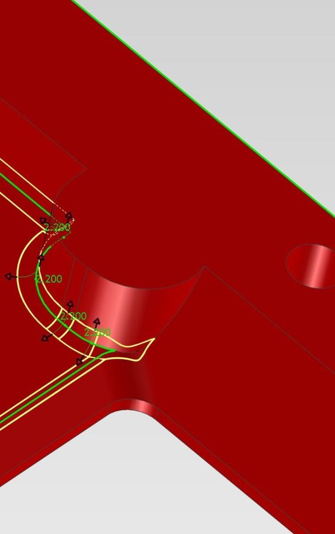
I ended up getting this a lot better however I would be interested to see if you can squeeze a larger blend on the side without the opening. Where the opening is I've hit my target (3.2mm was the machinist request), but on the side that is enclosed / hollowed out the best I can get is 2.1mm. It's not unacceptable by any means but just trying to work with the machinist to reduce machining time and cost. Model attached and thanks so much for taking the time to look! Adaptor Plate.ics
-
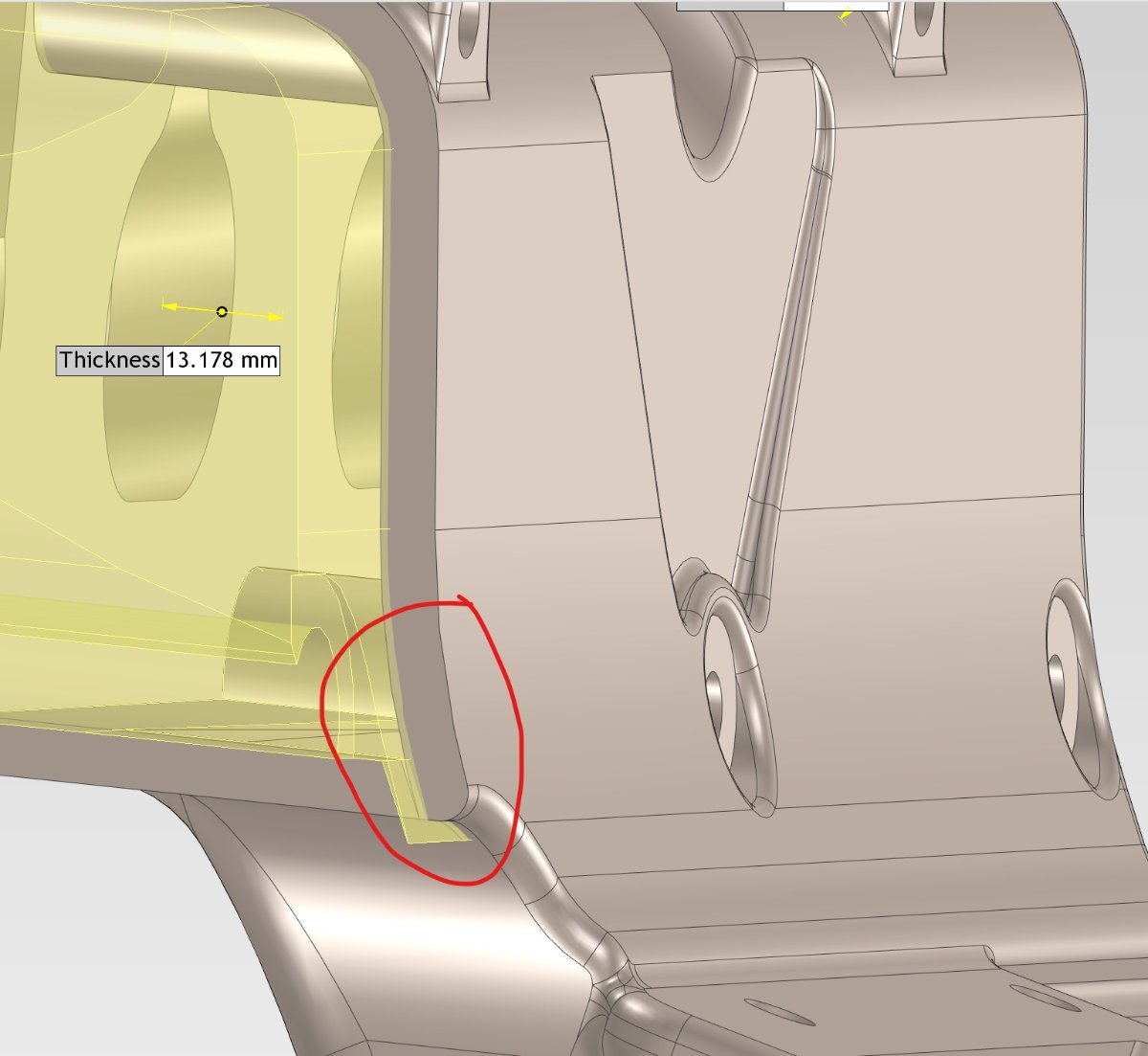
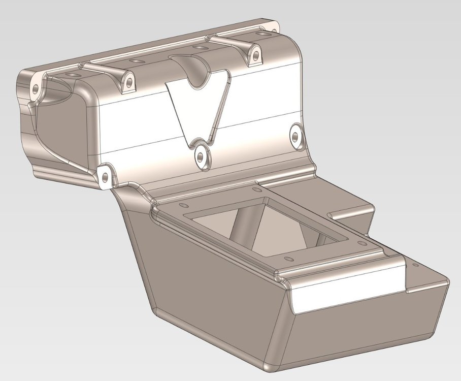
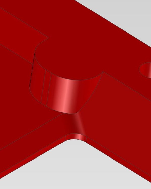
Hi guys. I'm having problems blending some challenging edges and wondered if anyone can see a way to overcome it. I can do a small blend successfully, but from a manufacturability point of view, my machinist is telling me that I could save a bunch of CNC time if I can make the blends larger. Stands to reason since he can rip into it with a larger tool and not have to resort to tiny tools and multiple operations. Here is the area in my part that is causing grief. I can understand why because the intersecting geometry is quite complex - I have a loft with a fillet and a cylinder intersection right in the corner of the loft, and there's a nasty point sharp point that complicates matters. But since there a number of blend options in IC that I don't fully understand yet I thought I'd ask and see if anyone has any ideas. Area of part as follows: Capture 4 is the closest but I'm not able to complete the blend all the way to the top of the boss. I'm still trying different sequences of blends and other things but results seem kinda random. Cheers...
-
I just went in to check the mouse settings and software asked me to install an update. Did that and now it's behaving as expected! Thanks for the tip! Appreciate your quick responses....
-
Hmmm, I'm not double clicking. I've only noticed this behavior since upgrading....
-
Thanks so much for that. One other thing...the behavior where it zooms to fit and centers - sometimes if I'm zoomed right in and want to rotate the part / scene, zooming to fit is not what I want. Can this also be turned off? Thanks again for your help! Appreciate it!
-
I've noticed that the scroll wheel works differently in IC2022. I'm actually finding it a bit annoying. When you click it zooms to fit and centres your part on the screen which is kind of cool. But if I'm blending (for example) and I rotate the part to get to an edge it auto completes the command making you go back in and edit or start a new blend. Is there anyway you can turn this off?