


wile e coyote Genius
-
Posts
39 -
Joined
-
Last visited
Content Type
Profiles
Forums
Blogs
Downloads
Articles
Gallery
Everything posted by wile e coyote Genius
-
Thanks IronKevin.
-
Hello: I have an idea that can improve the copy function, especially in non-regular arrays. I'd like to know how and to who I should submit my idea. Thanks and regards.
-
Hello: I have tried using the "options" and "customization" commands but I can't find a method to modify the Ribbon Bar. I have an issue that occurs some times when I select a part or shape. Many times after I selected the item I then want to launch the Tri-ball. I like the concept of clicking on the tri-ball icon next to the part but many times the icon gets stuck behind a handle when selecting a shape making it extremely difficult to select. Also, if I select more than one part the icon disappears. In both cases the solution is either using shortcut keys or selecting the tri-ball icon (very small) at the very top of the ribbon. Some of the tabs in the ribbon (like Assemble tab) have a large tri-ball icon available. I would like to modify the ribbon so that the tri-ball icon shows in all of the tabs. Does anyone know how to do this or if it is possible at all. Thanks and regards.
-
Thank-you Jonas and Malcolm. After much contemplation and further digging I decided to take the long road of creating the flat portion with the notch as a single, filling it with the required holes for the switches it covers and then created a single part/intellishape which I then dropped onto the flat part. I then made copies of the dropped part. While that has worked, what could have been a 1 hour job and turned it into a six hour job. It is done and I have come up with an idea of a new multi-copy feature that can be a real time saver. Just got to figure out how to convey it to the appropriate IC engineers. Have a great day everyone.
-
As I have indicated in previous posts, I have been using Ironcad since V1.0 and actually before it had the 2 kernel capability.One of the functions that I used quite regularly and now use very rarely. In the early days when the user booleaned two or more intelllishapes the new part would take on the name of the first part selected and all of the shapes that made up each part were listed individually based on the order inwhich the intellishapes were selected. It had the capability of allowing the user to move the shapes locations up and down the Scene Browser which in turn modified how the booleaned parts interacted. At sometime the operation changed to the way it works now where the new part takes on the name of the first intellishape selected then instead of showing all of the shapes it shows all of the shapes of the first object selected followed by the actual intellishapes as single items. In this scenario it is impossible to move the position of the intellishape components to different locations in the Scene Browser. I am wondering why the function of the Boolean operation was changed and if an Ironcad engineer could address it. The old way had advantages over the new way which makes me wonder if when doing a Boolean operation there could be an option in the pop-up window to select the old way versus the current way. Having that capability would really solve one of my issues. Thanks in advance and regards.
-
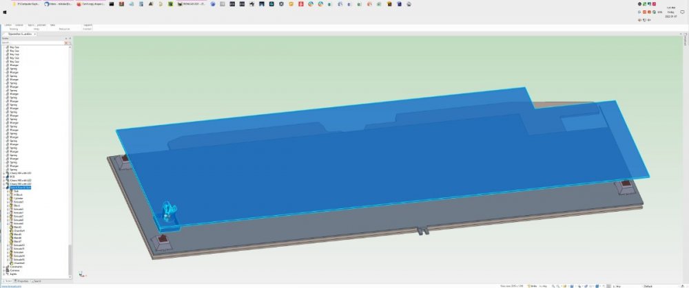
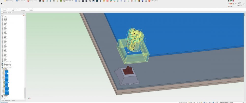
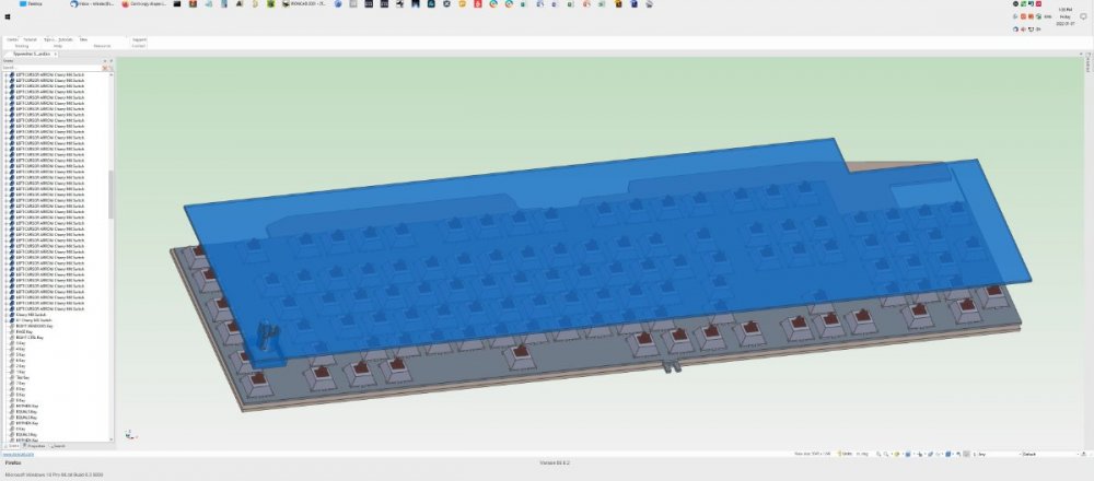
Hello Jonas and all others who have replied. If you look at pic 1 you will see a large flat plastic plate with additional shapes in the lower left corner. In the scene browser you will see the top intellishape highlighted. Pic 2 shows the components I want to copy. You will see them highlighted in the scene browser and you will see that the items selected include both blends and chamfers. In the example Jonas provided it only showed adding a single radius to the hole whereas my components have several bends and chamfers. Pic 3 shows all the switches that the shapes highlighted in pic 2 must line up with (over 100). I guess my only solution appears to be creating the flat sheet with the notch as one piece and create the other shape as a part and place multiple copies onto the sheet where needed. Thanks to all who replied and like I said maybe Ironcad can find a way to move/copy the blends/chamfers when a part/shape is moved. Best regards.
-
Thanks for the input guys. I will look into those suggestions. I have been using Ironcad since version 1.0 and the issue has been around since then. What I don't understand is why Ironcad hasn't addressed these copying issues. Sure would make things easier. Is there a way to make an intellishape out of selected shapes? I tried creating a group but I couldn't copy the group with the triball unless the blends and chamfers were not included in the group. Unfortunately all of the copies I need to make are not in a regular pattern for array. I got a couple of ideas but the amount of work will eliminate all of Ironcad's advantages. Maybe a future version will be coded to handle the move/copy triball functions with respect to blends and chamfers. Regards
-
I am developing a new modification for an existing computer keyboard but I have run into a problem. I have created a structure by dragging and dropping various shapes together to create a desired part. I now need to copy a collection of those shapes which also have blends and chamfers about 100+ times. The problem is that if I select the blends and chamfers along with the shapes they have been applied to there isn't a triball option and thus no copy option. If I remove the blends and chamfers the triball is available but at this level if I make the copies it means I have to go and place the blends and chamfers over 100 times (take forever). I can't find any way to allow me to copy parts with blends and chamfers unless you are copying the entire component and in my case I am trying to copy a portion of the part. I am wondering if there is some reason why Ironcad cannot copy a shapes with a blend or chamfer applied to it. I would think that it would be a no brainer. Anyway, looking for advice on how to solve my problem. Thanks and regards.
-
Creating multilayer coils
wile e coyote Genius replied to wile e coyote Genius's topic in General Discussion
For all who care, I forgot to sign-in and thus the "guest" indication. My stuidity. -
While I have no issue creating coils for springs (single layer) but I have a need for creating a multi-layer coil (think coil wound on a relay bobbin). I know I could create a solid that is the size of the coil but for presentations it is better to show the individual wire strands. Can anybody tell me how to create a multi-layer coil. I also realize that I could create a 3D path to use to extrude a wire but that would take forever to create. I am looking for a smart object like the one used to create helical coils in the Tools Catalog. Any information is greatly appreciated.
-
Custom hole tool thread representation
wile e coyote Genius replied to bmckelvie's topic in General Discussion
I am using the 2016 version with updates and it has the same issue as indicated above. Since I work independently I just know that the hole is threaded and have accepted it as normal but as can be seen in the above notes it obviously is not normal. I was wondering if there is a file to download for V2016 or could I just download the 2020.reg file? It would be nice. -
Hello IronKevin: Will there be a way for me to obtain the fix if there is one? As I am using Ironcad 16 I don't have any support anymore. The reality is that I am only creating things for myself now that I have retired and the reason I can't justify spending the money to upgrade to the current version. If a fix is generated it would be nice to get it. Thanks all.
-
Thanks rsaucier. While following your instructions it worked but it also allowed me to modify the original Bend Line Callout style. On the other hand, while your instructions did work and I can use them for further style changes I am confused why it didn't work using the properties window. Again appreciation for the assistance.
-
I created a sheet metal design that has a variety of bends. I then flattened/unfolded the design and opened a new drawing. Using the "Standard" icon I created the views I needed and clicked OK. The result was the required views showing the "bend line call-outs" and bend lines. Unfortunately the text of the call-outs is too big and need to be made smaller. Seemed simple, select the call-out then right click the call-out and select "properties" in the pop up window which I did. Now I have the properties window open I select the "text" tab. I highlight the text and then click on the arrow for the font size. What happens is that the text is not highlighted but the value in the size selection box is. I type in a value of 6 (one half the default size) and hit enter and the text is shown highlighted and smaller in the options window. I click the apply button and nothing happens so I click the OK button which causes the options window to close but the text in the call-out does not change. It gives the appearance that the font and its size are locked. They are located on the "Base" layer which is NOT locked. Not that it should matter but I am using V16 SP1 as I can't afford to update to the new 2020 version. Any and all help with solving my issue is greatly appreciated.


