


ITAYLOR
-
Posts
101 -
Joined
-
Last visited
Content Type
Profiles
Forums
Blogs
Downloads
Articles
Gallery
Posts posted by ITAYLOR
-
-
What is the best way to get a wire frame scene 'without edges" to export to a high quality export image.
If I select export image (or render), the result is full colour. All I can do is screenshot the display... which gives a result that fuzzes out quickly when zoomed.
A graphics specialist needs the quality to make an "assembly manual" of an exploded view I created. He imports to adobe software.
Any tips welcome. Thanks.

-
Belated reply... been away.
I was very new to IC then... To Toms question... I was referring to nested blocks in AutoCAD LT like multiple blocks inside blocks. I was hoping a part in a part would disassemble. I now understand 3D may not be the same concept.
Thanks Cary... took me a while to grasp the how to... I still mess that up at times by drag drop with left mouse habit... and wish that if I created say a PART1 = [SLOT + CYLINDER] in the scene file tree, How good would it be if I could 'free up' that 'part 1+2' and drag the Cylinder out of the file tree separately so they become two separate parts 'Part1_slot' & 'Part 2_cyl'
IE. File tree would then read PART1 [SLOT]; PART2 [CYLINDER]. Wish list.
---------------------------------------------------------
NEW WISH LIST... RADIAL PATTERN... [posted here as key search word EXPLODE showed this post...]. Similar issue.
RADIAL PATTERN [placed in this post because it does not explode/disassemble].
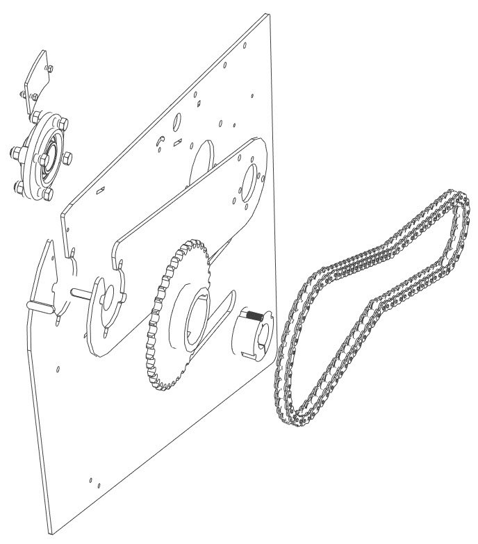
ISSUE: I used radial pattern [tri-ball/rotate/radial pattern]... to multiply a 1 inch chain link around a 38 tooth sprocket [19 links @ two teeth per link]. In design phase I wasn't sure how many chain links I needed to match the incoming and outgoing chain angle, so I just filled the sprocket to show link on all teeth and hoped to delete other unwanted chain links later. I want to EXPLODE [AutoCAD 2D talk - what is IronCAD equivalent? perhaps Disassemble?] the RADIAL PATTERN.
I want the links to be separate, so I can play around with different chain angle configurations and leave what links I need... and not be stuck to the radial pattern [which seems uneditable except for change nuber/angle/radius . When I arrive at a final design I may want the radial pattern in tact... but for now I desire flxibility to disassemble design/ redesign/ and fine tune.
Picture this: In the Scene file tree, the DELETE option is greyed out for each chain link. Is that the way the tool or is there something I can do to make all links their own separate entity so to all deleting.
I know there will be work arounds, but if there is a way to EXPLODE [Disassemble] the Radial Pattern so that instances are no longer dependent... If not, happy to live with it but just don't want to give up trying just yet.If so, I would love to hear about it. Enjoying the learning curve! IronCAD does some really amazing things.
-
Hi all
Preamble: Following my hiatus, hello again.
A few months ago I finally subscribed to latest IC upgrade (with imech and keyshot) but as yet haven't had a chance to even check it out. Looking foreward to a new learning curve this year.
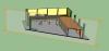
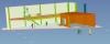
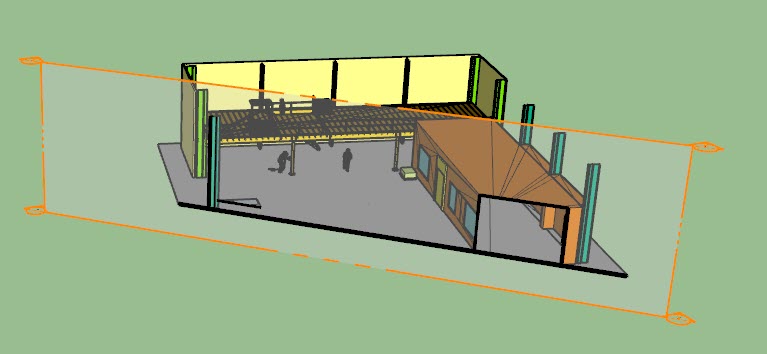
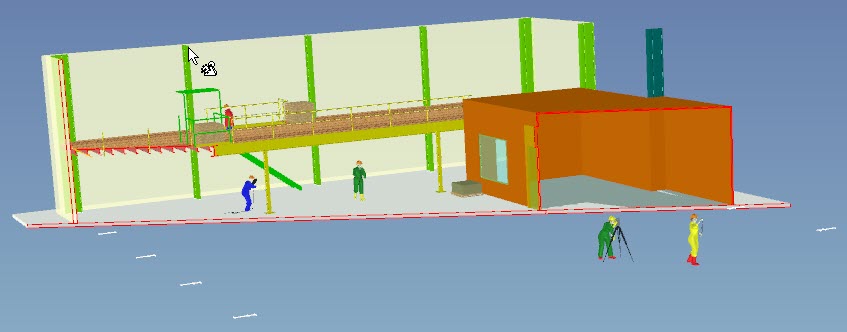
LAST YEAR I was asked to design a conceptual 3D model of a World War 2 style 'gun shelter' to cover an existing WWii gun at an ANZAC memorial centre. Interesting project, lets see what IronCAD can do!
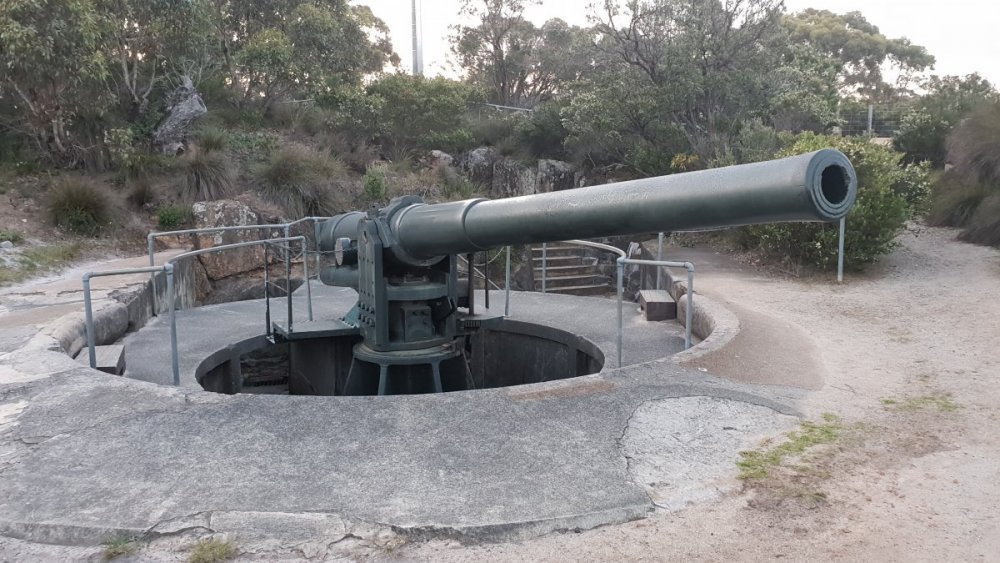
Photo above doesn't show original footings but I needed to ascertain where their true R.L. heights and spacial locations are before commencing design. One thing led to another... enter Chris, a genious who does Drone photography and aerial mapping. Check out this wow link.
Chis sent me the oringinal file of this project [huge size with all image tiles] so that I could use its spacial geometry points to locate the footings instead of trudging up the hill with dumpy level etc.
I managed to import the huge file into IronCAD, but found the drone technology seems to be surfaces, not solids [thousands of images to make a real 3d representation]. In Chri's software, the footings are accurate to like a millimeter, so I assumed I could just load the model into IronCAD and start drawing. But not so... I don't seem to be able to get IronCAD to recognise any surface, can't get it to click to anything like Chris's software that produces the moidel.
To help get your mind around his drone software, Chris also aerial droned an Alumina refinery (or Aluminum to you guys, is it?]. The drone photography gave a walkthrough model from the the huge building, even inside down to platforms and even to the fine details of pumps and electrical switches etc. As it happens I once worked in that refinery and knew the size of the nuts on the pumps, 32mm, incredibly his program measured them at 31mm - not bad for a fly around 9with thousand of photos assembled into a 3d model]. All a bit beyond me, I may bail out yet?
I bailed out of the job as another drafty beat me to it by submitting a beautiful concept drawing which impressed the stakeholders, but he is only good at 'Concept' design and not so great at actual nuts and bolts fabrication to the mm stuff. We still do not have the actual footing locations. I do have them inside the drone file but am unable to get IronCAD to read them. Surprised, last week I was offered possibility again to do the job as thge concept guy supplied no REAL data.
Other than a few concept projects and one real fabrication job involving a dozen steel columns, this would be my second real job using IronCAD 3D. Learning to love it by the way.
REQUEST
After 4 months working out woop woop I will be away another week... but thought I would just put this out there as a challenge to see what IronCAD can really do. I am sure ther must be a way to read the drone file.
Is anybody willing to have a go at downloading the Drone file of the gun drone model [if I uploaded it to say Google Drive for you to access - its large], and see if you can find a way to attach an IC shape [eg Slab drag and drop base plate] to the footings in the pit of of the model... ie. the cannon concrete foundations. If we can do that, I think I can find a bit of future work for my IronCAD and Chris.
Thanks from the bottom of downunder
Ian
-
Awesome :-)
-
I am working my way through exercises in an old Tech Drawing book (pp.121-144 by A.W. Boundy) to get me up to speed with 3D modelling. My intention was to retire as a work from home 2D drafty but a firm I draw for pressured me for 3D content (as their competitor has gone that way - Solidworks)... so at age 58 I purchased my first 3D program (Sketchup)... and now here I am IronCADing "better-faster-funner"). ... sometimes!
The excercises are forcing me to learn loads of 3D tips n tricks and are a lot of fun actually... IC really is a wow modeller (never enjoyed drawing these same shapes as much with pencil and set squares when I was at college in my tradie years), now my kids are going wow dad... that's cool!
The ultimate goal is to learn how catlogues work, set up an automated title block in CAXA that will read the "part Name" (which is the order I want them to appear in the catalogue) so that I can pop out a batch of drawings in the same order as the Tech Drawing book (that will correspond to my catalogue).
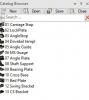
I guess I can rename them with a nemerical prefix; RMB/Arrange ascending..
Am I heading in the right direction? Further catalogue tips n tricks welcome.
-
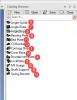
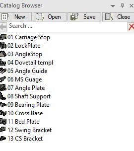
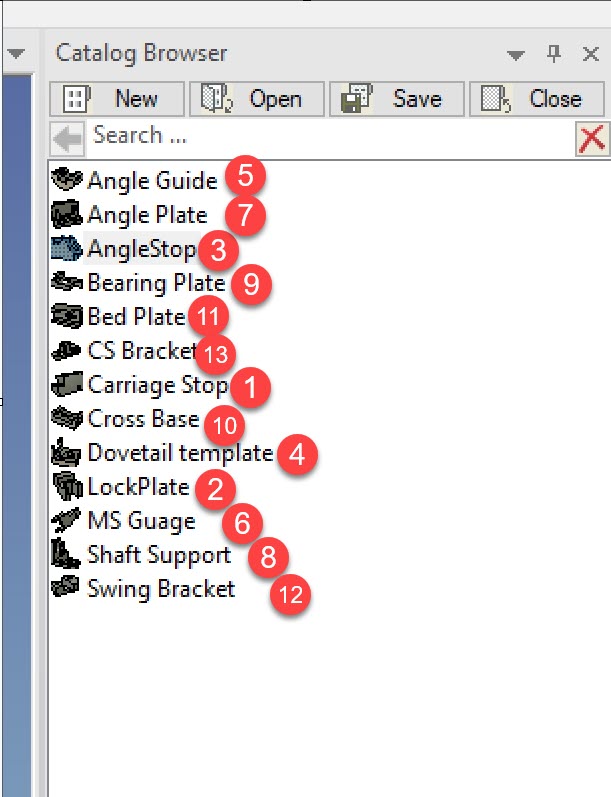
Can i rearrange the order of items in my catalogs without changing the alphabetical names?
I want the order to look like this:
-
-
I am pasting soembody elses tip here because its brilliant.
PWatson posed a good question in general discussion and got a great answer... by Peter [bstaff]...
The "Technical Requirement Library" is quite useful actually (given that Caxa text is lacking a few essential features) I thought it worthy of indexing in my own help files.
And you wont find the answer in the Caxa manual:
So I found a way to convert worthy TIPS to PDF [which I am sure the authors wont mind us dummies saving for the good of 3D posterity]; Here is the DIMENSION tab/Technique Requirement Library tip:
Numbering_Text_Lines_TechnicalRequirementTool.pdf
My subsequent tip is that good forum tips can be converted to PDF.
1. On the community forum page that has a brilliant answer, copy the browser address to clipboard.
2. Goto "Convert to PDF" website: https://www.web2pdfconvert.com/
3. Paste clipboard info into PDF CONVERTER box.
4. Convert... done!
WISH LIST...
include technique Library knowhow in next Caxa manual.
-
Most programs have a 'Repeat last command' hotkey. AutoCAD uses spacebar... Corel draw apparently uses Ctrl+R. Maya does it... Sketchup use a plugin "Recall Last Tool"... etc. And Caxa uses space bar.
I have attached an IronCAD hotkey list... as far as I can see there is not a 'repeat last command' option. IRONCAD_Shortcut_Keys.pdf
Cant find in IC help either [http://www.ironcad.com/support/OnlineHelp/Funnction_Key_Reference.htm]
Does anybody know a hotkey tip that 'repeats' last command?
-
Thanks Joli
That has absolutely made my weekend mate!
Another arrow in my 3D quiver...
-
Hi Ian,
You may opt to select all parts (intellishape) all highlighted as yellow, do right click and select combine as one part. That will allow to have that fillet. Usually what I do I also have the parts construction, copy it and suppress it as a base reference model for future revisions. On the copy, I do all the modifications or combine them all together.
Hope this what you have in mind.

Thanks Joli...
When I select intellishape yellow, there is no 'combine as one part' option in the RMB options.
Scene attached if thats any help.
-
Firstly... apologies for my asking questions in tips and tricks previously (I now see that is for 'completed' tips only). And as always I am hesitant to post as I respect your time,,, yet again I have tried long to find a solution elsewhwere before posting here as a last resort.
Just when I thought I had the fundamentals of drag and drop sorted out, I end up not being able to 'Blend' a part with another block. I hope the video works... It should be self explanatory...
Basically my question is... If I right mouse drag and drop as a 'part' into a scene... can I later on convert that part to behave like a left mouse drag and drop intelishape...
Video
Blend_Part_Vs_Intellishape__1_.mp4
Save as to view (if video fails online)...
-
I created a simple model with new drag and drop parts and your tip works perfectly. Useful tip - thanks!
I think my large model is corrupt. I tried background (Ctrl-A) and it selected everything ok... but the Tools/Section_(Part/Assy) was still greyed out (as was the Feature/Assy tool).
The workaround was to 'Select all'... then, RMB in active scene browser/context menu allowed Assembly... Everything ASSEMBLED into one file ok, which allowed a SECTION command... Alas, this particular model has become clunky to edit and other glitches hindering me.
Time to give up on this model... Not only did I change US steel sections to Australian standards mid project, I have possibly over experimented... but learned loads of good stuff along the way. Thanks again for the tips.
-
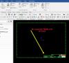
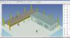
New SECTION problem. I have built a larger and more realistic model since first post.
Using the TOOLS/SECTION Part/Assembly tool... to place a section through the entire model, requires my model be an 'assembly'.
What if my model will NOT assemble. How can I SECTION a view through the entire model?
I can select an assembly (within the model)... But it will only show a section through that assembly (not the whole model).
Can someone show me how to "assemble" the entire model so the TOOLS/'SECTION tool' will work.
My model...
If I select all - the assembly tool is greyed out and I cannot assemble the model.
19634_K_R_Mezz_4__PurlinsFlush.ics
EDIT POST: I have since discovered that if I select all (everything in the scene)... even though the ASSEMBLY icon remains greyed out (forbidding me to assemble)... If I Right Mouse Click the 'active' files in the 'scene browser'... suddenly it knows I want to 'assemble' the selected files, and activates the 'assemble' icon both in the RMB context menu and on the icon on my ASSEMBLY tool set..
So I guess thats problem solved...
PS: As a test... The unassembled model was exported to SKETCHUP as DXF... Imported and SECTIONED first go. There were 420,000 surfaces (so I know we are asking a bit... but it coped.).
No need for reply... I have left this here for the benefit of others.
Summary...
1. A SECTION requires the model to an ASSEMBLY
2. To assemble an entire large model, RIGHT MOUSE CLICK the active files in scene browser
3. Goto TOOLS / SECTION (part/Assy)
-
Hi Ian,
Select on the Tab of the washers. Look below the image that shows the bolt and washers and you will see a check box labeled "Active". If that is checked, it will build the washer. So just select those tabs and uncheck Active to remove the washers, nuts that you don't want created.
Best Regards.
Cary
Thanks... that worked

-
Lucky you can't drop the toggle in this post or your name would be... Jonas@Hollowmakarna
It worked a treat, thanks for the tip [Are these post printable?].
-
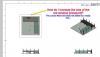
I chose this outdated post only because it was the first to appear in my search for "Fasteners"...
I have 2018 IPROFasteners... The IronCAD training on this [see: https://ironcad.com.au/training/] shows a Fastener addon but it only has TWO washer buttons [2 washers is what I want but that tutorial is 2016 and the IPRO interface is different].
My Fastener addon [2018] has "Four Washer buttons" [not two]. It seems impossible to remove one of the four washers... If I have a 1000 bolts in a job, I dont want 1000 extra washers in the BOM.
Please see video...(hope it turns out" may have to download to view (?)
Warning... Download video as it only plays the audio whenlive online)
Is this a bug.. or me?
PS... I really have researched this before posting.
-
FRUSTRATED... getting to point of wanting my money back and deal breaker...
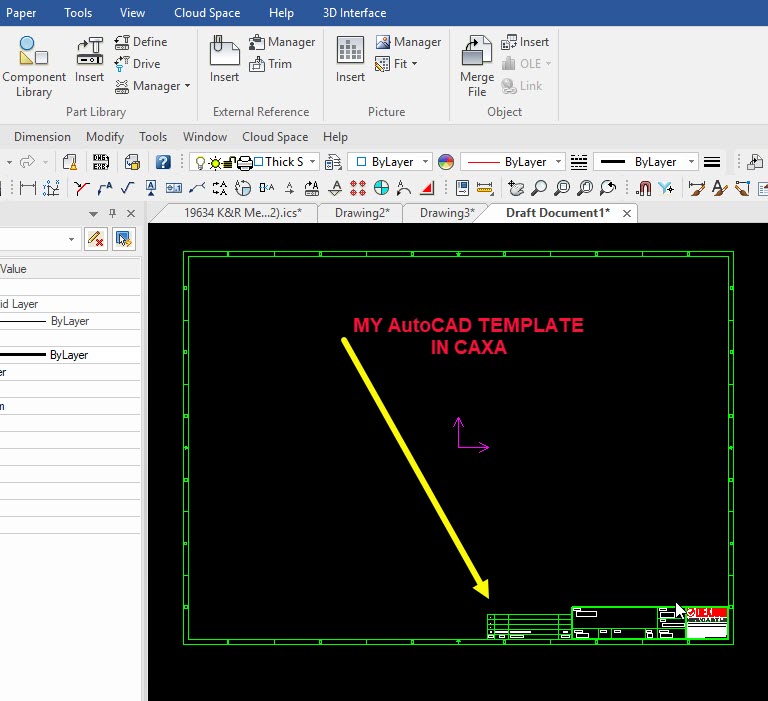
My goal is to create a decent working Template [EXACTLY as my AutoCAD template looks that I have used past 4 years and Client loves].
I imported it to CAXA successfully.
It seems I cannot insert a cad drawing (or autoCAD native objects] direcvtlty into the 2D Drawing Environment.
-
Hi All,
Our community of users is a strong and actively growing community. In order to help continue our grow and the IRONCAD brand, we would like your feedback on the success of our products in your environment. Please visit the Customer Success Form to enter your successful usage. This information will be reviewed and signed-off by you prior to spreading onto IronCAD's website to help promote IronCAD as well as your Company. In addition to the marketing of your company, you will be entered into our drawing at the end of the year for an award for your efforts!
Thank you for your participation and help to keep the IronCAD name strong.
IronCAD
Posted 2011... Hmmm?
Where are the reviews from all the advertised success story clients?
2018... for me
I have had SOIME SUCCESS of sorts creating a model.
I don't mind IC modelling environment
LITTLE SUCCESS yet mastering the 2D Drawing environment.
I am going nuts with this...
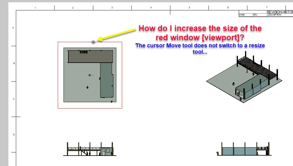
Eg. 2D Viewport seems locked.
The Template border objects are NOT LOCKED (The stuff I want locked - or BLOCK if autocad)
The viewport [Window?] is LOCKED (but I want that UNLOCKED).
Simple ask!
How do I edit the viewport window... I simply want to drag the corners diagonally and make it larger (then scale the content manually to get more image on my wasted white page area)
Tips welcome
-
Is it me or the program.
A simple thing like Disassemble too many times... and I disassembled a level too many eg. my "Fastener Assy's" and my bolts became little bits. I thought, ok... UNDO... But it does not work.
So many things in IC are like this... In Sketchup I can undo for ever. Is there a way to solve this?
Hopefully I have something set wrong!
-
EXPLODE command equivalent?
In other design programs where a block, component (or LINKED part] can be exploded into its separate blocks. How does IC do that?
Lets say I accidentally 'left click' a 'drag n drop' item...
then add it to an exising item in my scene [Vs Right Click drag n drop which I should have done]...
But after shaping my object realise it should have been a right click drag n drop... because when I click one part... they BOTH become blue [selected].
How do I EXPLODE the two parts to become separate parts... r than mud
My video did not work sorry.
Try this one... {Dang... Have to SAVE to file to view on my system]
-
Hidden in plain sight
 That is exactly the go!
 Till now I only 'linked' features like H-blocks etc., inside an 'assembly' (or 'part' ?)...
Chuffed
 Thanks Cary...
 -
You can also go to the "Edit feature options", change to "Add Material". Move the tri-ball to the desired location, and then go back to the "Edit Feature options" and change back to remove material. It may not be as quick, but I have used these steps for other things once I learned it was there.
RJ
Huge... another tip
These forums really are a wealth of knowledge.
-
I am trying to make a part that when copied... if I modify the part, all copied parts in the scene are modified and updated automatically.
ie. Trying to make it behave like an AutoCAD block... Or sketchup componetent etc.


How to change units in CAXAdraft?
in General Discussion
Posted
I opened a drawing (with many 2d parts drawn by client) with caxa, created in draftsight by client... then Copy 2d Shapes to clipboard [to paste in 3D Sketch).
Then In 3D SKETCH paste those objects. Result is Extrude is in usual mm size... but the 2D object I pasted is 25.4 times bigger. Frustrating.
Only workaround is to Export the part geometry from 2D file, save as a separate dwg, then import to sketch. I would love to be able to press a UNITS button to resolve this.