HDEAR
-
Posts
1,019 -
Joined
-
Last visited
Content Type
Profiles
Forums
Blogs
Downloads
Articles
Gallery
Everything posted by HDEAR
-
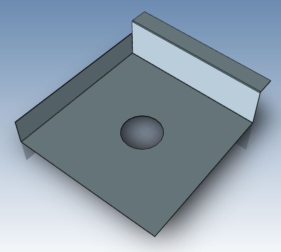
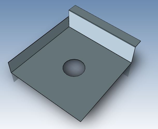
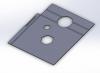
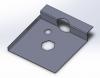
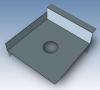
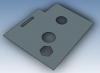
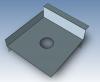
Many of our products use perforated or expanded metal screens and the like. One part for example is a nominal 1200mm x 600 mm sheet from 1.2mm thick powder coated zintec with 10mm folded edges all around and the perforated pattern on the flat part of the sheet is 5mm dia holes at 6.5mm staggered centres. The holes don't cover all the sheet, but even so there are 182 along the length x 96 across the width, making 17,472 holes in all. Then for one job, I have four of these screens to show, along with a whole pile of other sheet-metal work. What's the best way to do this without giving my computer constipation? I tried using a 5mm surface instead of the holes, thinking this wouldn't take up so much memory, but it took ages. I tried making a pattern to use as a paint-brush, but working out how to do this was a mission in total frustration and nearly ended with seeing how fast I could accelerate my computer through space. Any pointers anyone? How do you guys show your perforated requirements? Thanks Harley
-
This link refers to a video where a wheel is made from what appears to be a 2D file - jpg or pdf or similar. Being new to IC, I was intrigued as to how this was done. In fact, when I was convincing my boss to go with IC rather than SW, I showed him this example and it was a selling point. Sooner or later, I will be expected to do a similar exercise so I'd appreciate some help. Firstly, exactly what type of file was that he used and secondly, how do you get that file into a scene to start with? Thanks
-
Wow, what an amazing community! Thanks guys for all the input! I feel more confident about using IC now, especially being a newbie and coming across some challenges which may seem a piece a cake to the experienced.
-
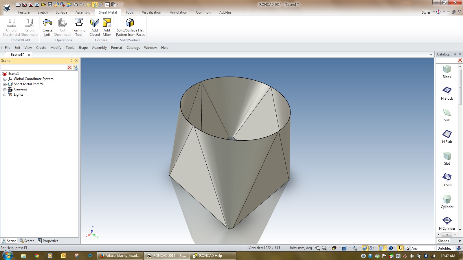
Well, in this case the material is actually not steel but plastic. The cylinder will be rolled plastic. The H Slot/Oblong will be cut into the plastic in the flat form. The area of the H Slots will be relational to a certain surface area at the bottom of the cylinder which in turn is relational to the diameter. In this case it's critical to control air flow into the bottom of the cylinder in relation to the cylinder's diameter/plan area. Therefore a precise slot area/diameter-hight area is required. It's not easy to control that by doing H Slot into the cylinder when it's rolled. Hope this makes sense. Also some of our punches are designed to create a certain profile when the stock is rolled to a certain diameter. Some may consider this is the tail wagging the dog. Hope this makes sense.
-
Is there any plan in the future to offer this?
-
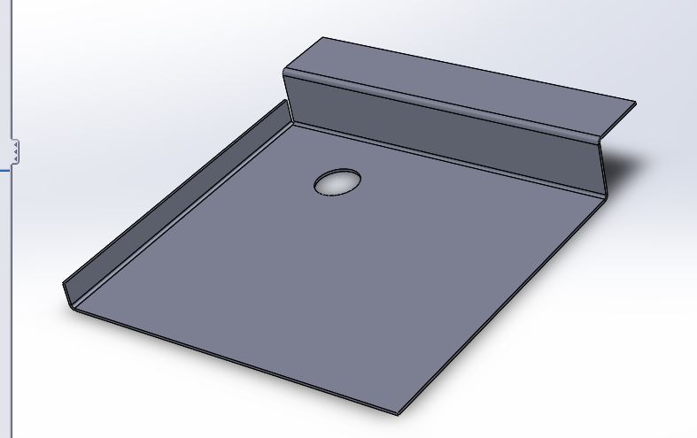
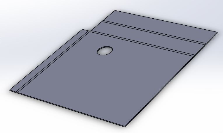
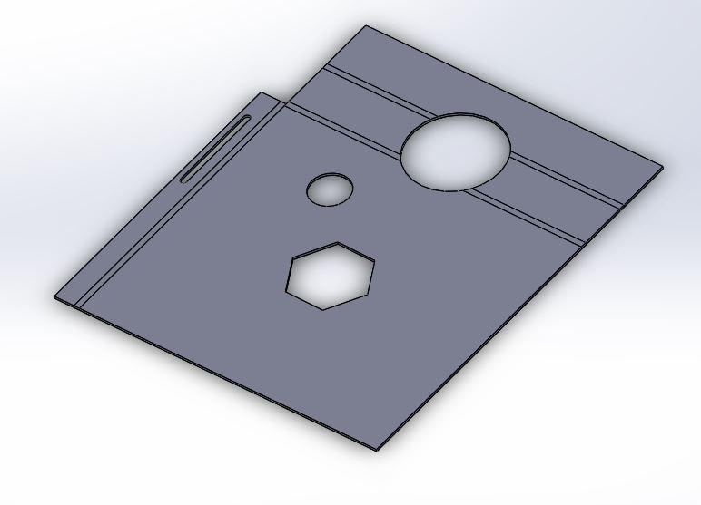
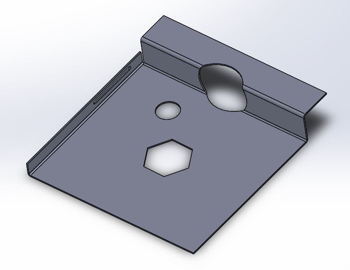
Here's a demonstration of what I mean. The first four attachments show a sheetmetal part made in SW. First pic is with bends and one penetration. Next is unfolded. Next is penetrations made in the unfolded part. Finally, refold, showing the penetrations that were added in the unfold position. Next four ( prfixed IC) are the same sequence in IC, but you'll note that when the refold is done, it does not pick up the penetrations added onto the unfold part. Also note that the fold lines areb't shown on the unfolded part in scene view - perhaps there's a button I should press to display that that I am not aware of. Any help appreciated. Thanks


-
Thanks. What do you reckon is causing this problem then :"I then tried adding s/m stock in a new scene, made a few bends, unfolded it, added H Slot and H cylinder, these appeared on the flattened sheet, but disappeared when I refolded." I'm wondering if I've got something set up wrong. I can't create a hole in a sheet of metal using extrude/remove material ( sketch on a face, then use extrude) BUT I can create the hole using Extrude Wizard. I wonder why normal extrude doesn't work and wizard does?
-
I tried this in a new file, following the cylinder/shell/solidfaceflat pattern as you describe. CTRL-K did not allow me to refold. I then tried adding s/m stock in a new scene, made a few bends, unfolded it, added H Slot and H cylinder, these appeared on the flattened sheet, but disappeared when I refolded. CTRL-K is making no difference. Something's screwy- probably me ??????
-
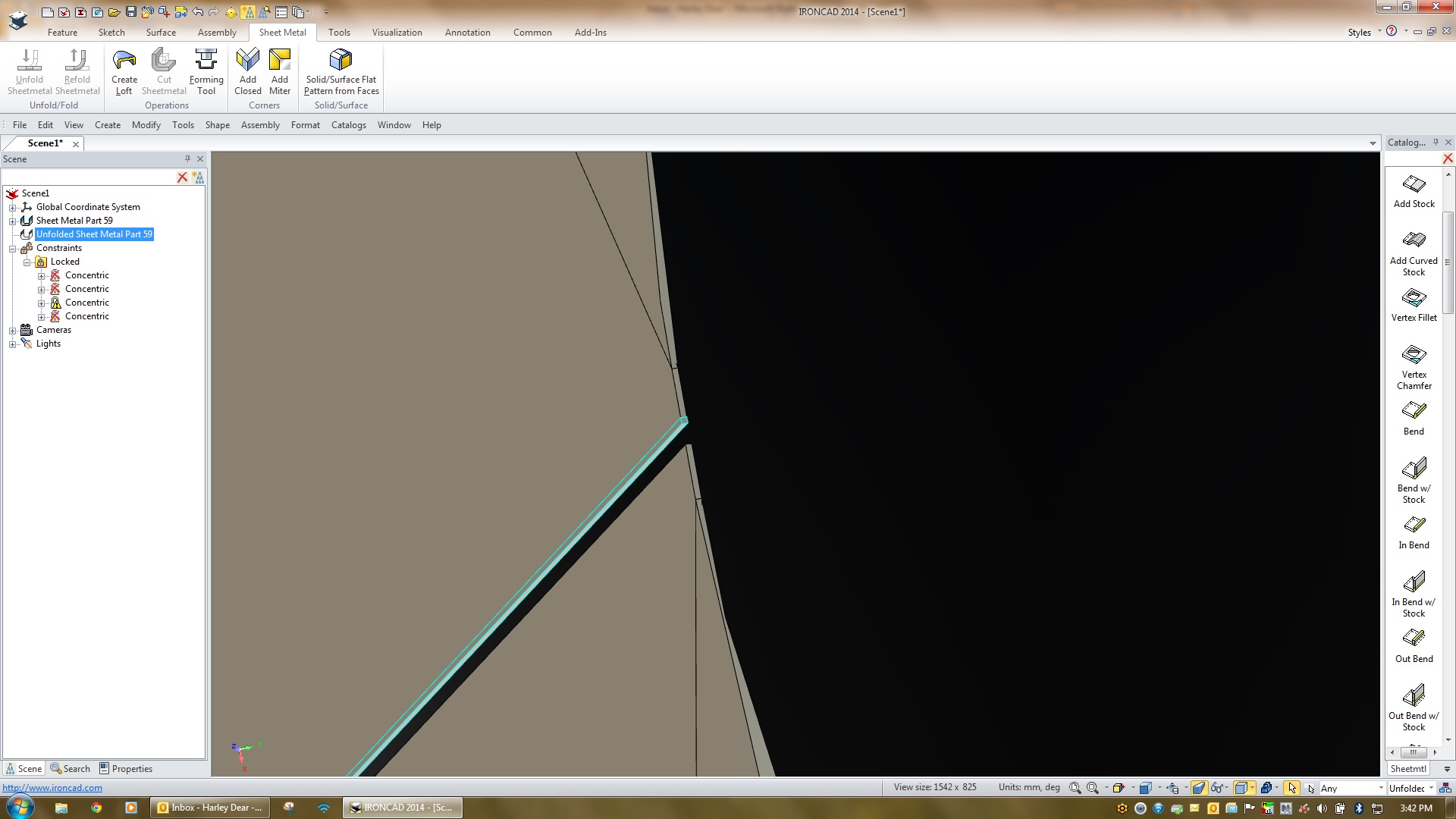
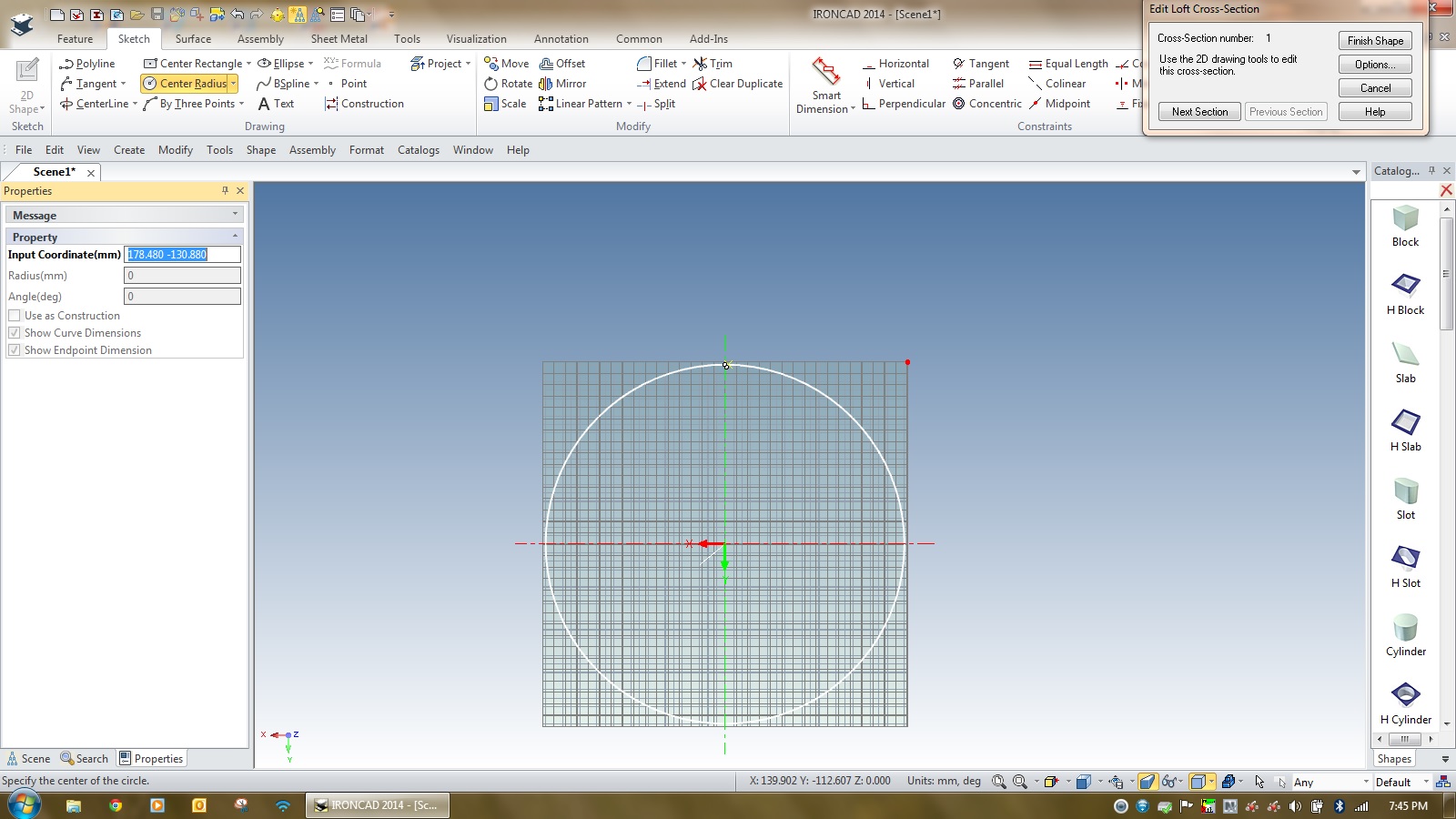
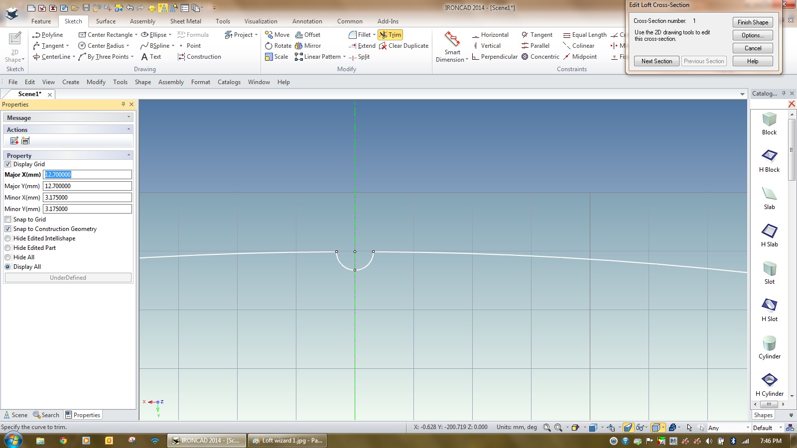
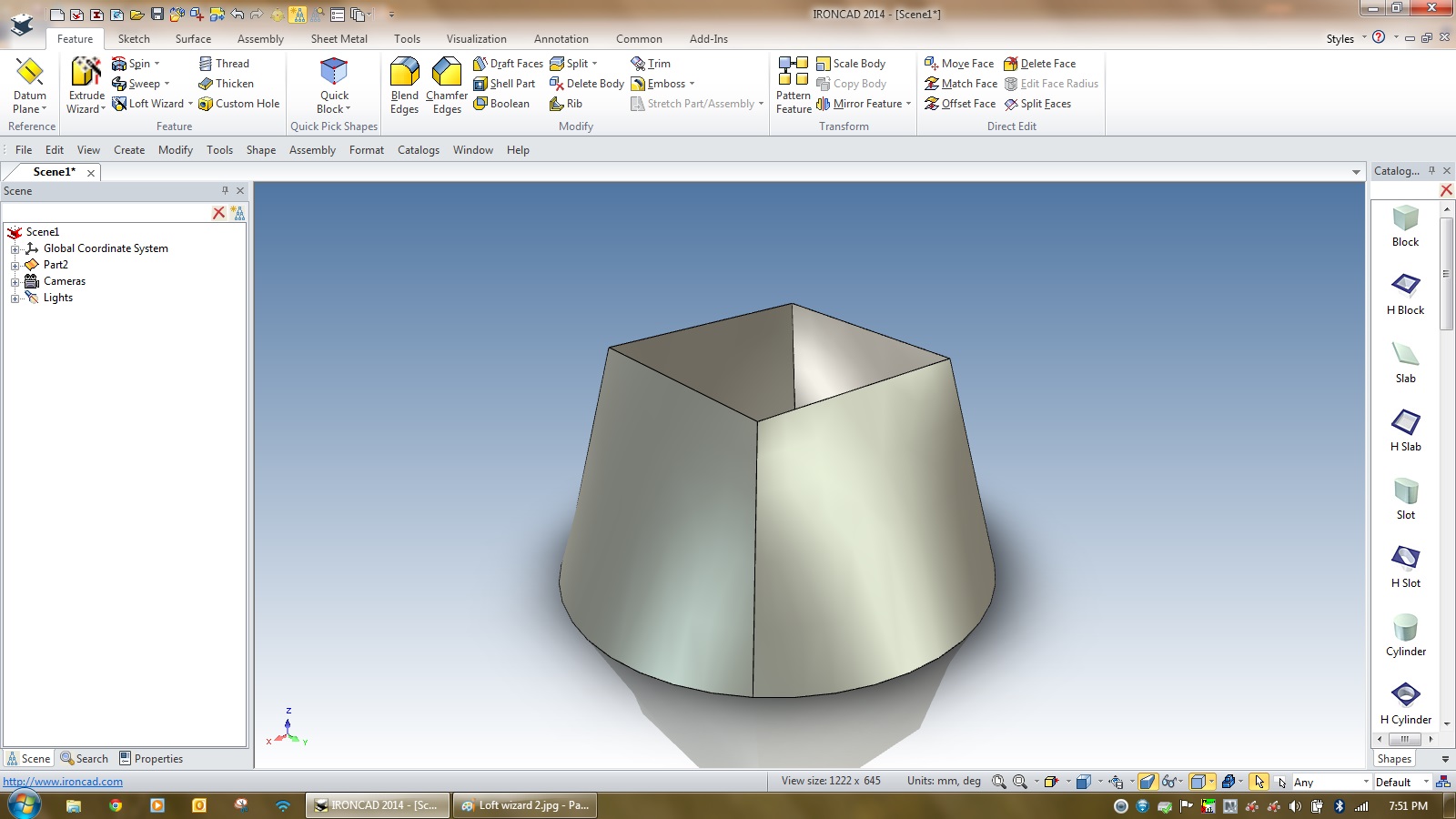
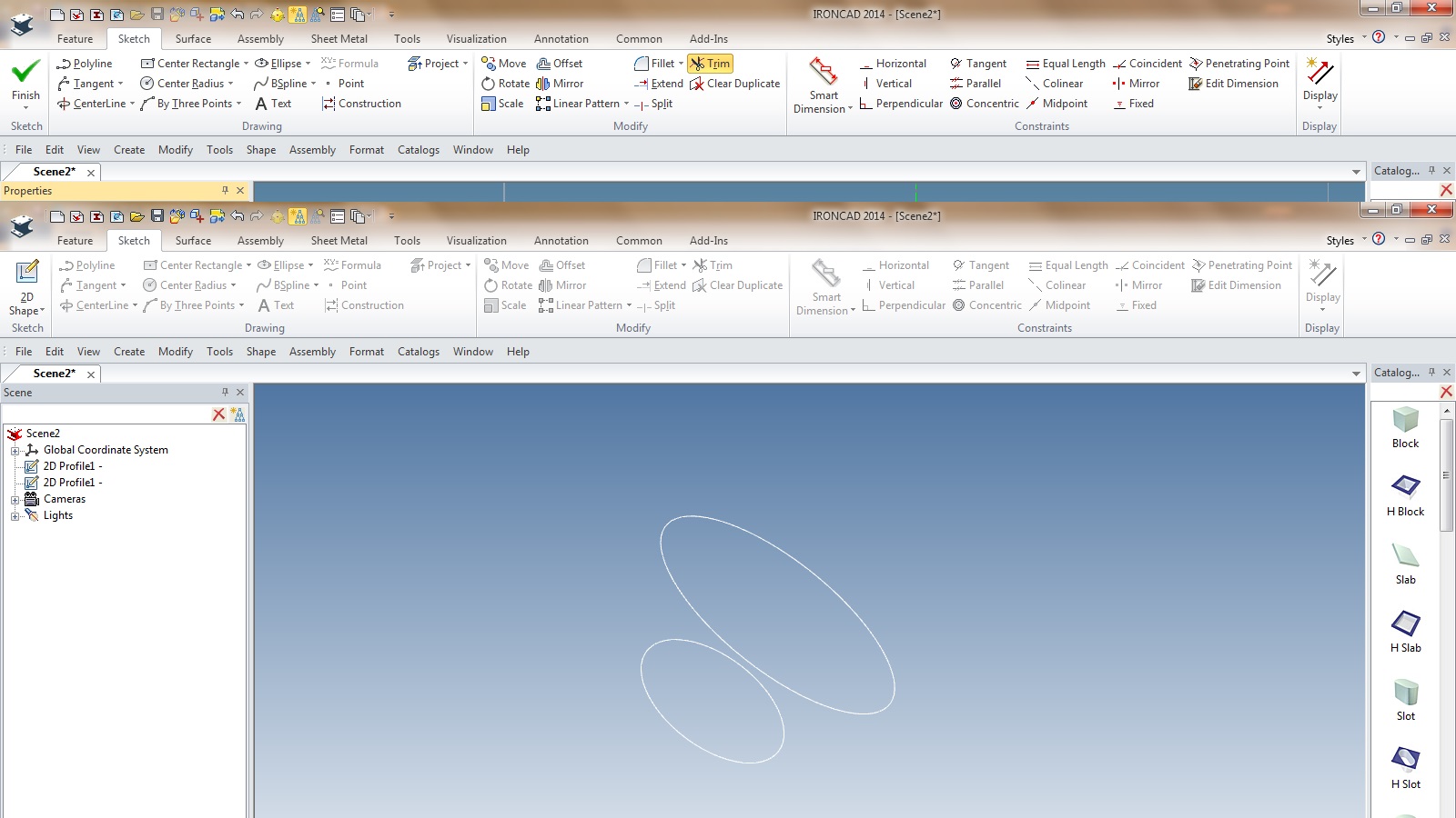
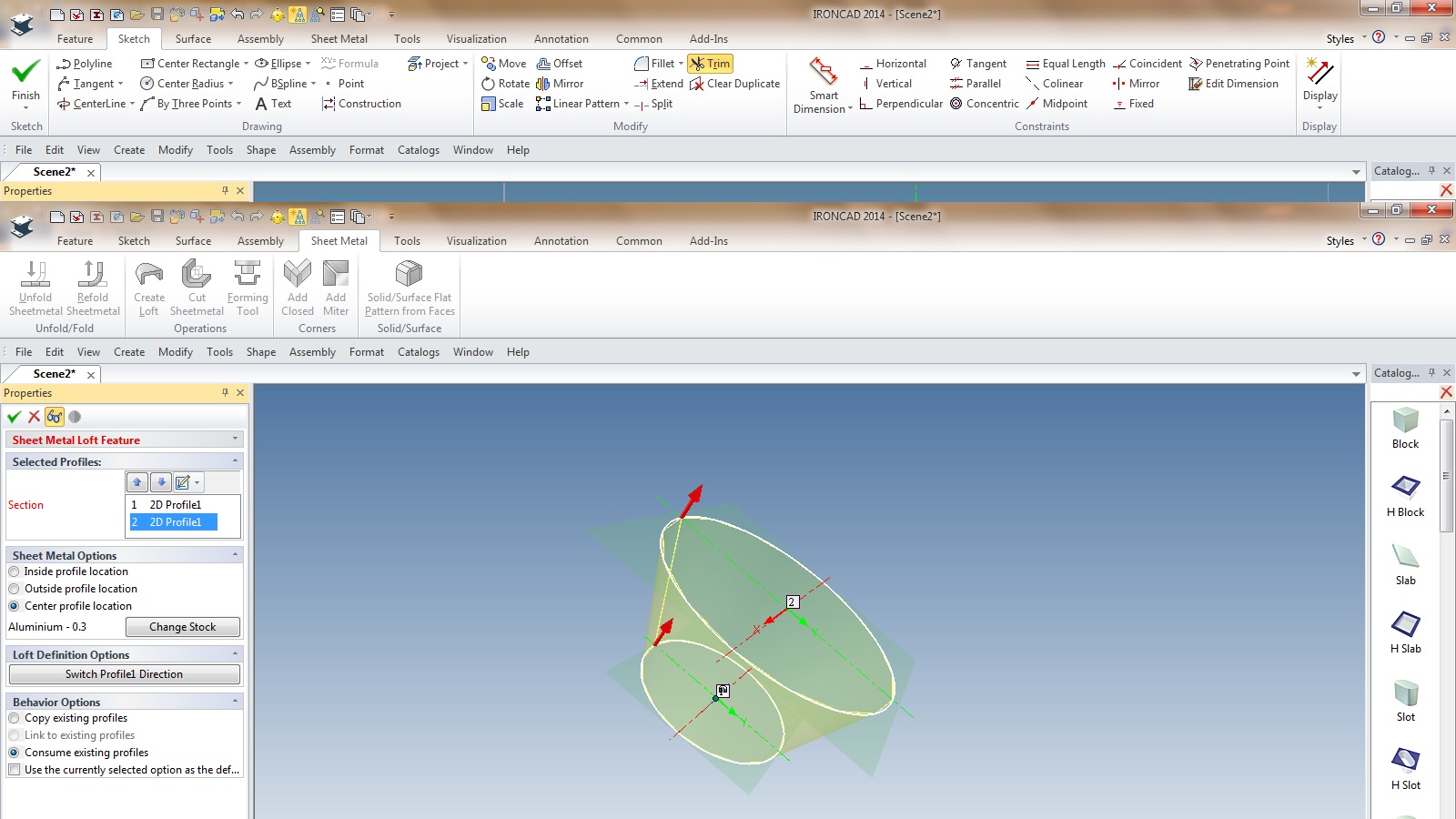
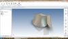
Ironcad 2014. I'm designing a cylinder in 8mm thick steel ( about 1000mm dia ) which will be rolled when manufactured. the cylinder is parallel, no taper. Around the perimeter of the cylinder at various heights and radial points, there will be holes and slots. These will be made when the sheet is in its flat form, prior to rolling. Using either ACIS or Parasolid for parts, if I use loft sheet metal to make the cylinder, then unfold the sheet and add H Slot and H Cylinder where I want them, when I refold, they do not show. Similarly, if I use H Cylinder in the cylinder's folded/lofted shape it appears when I unfold it ( which is ok ) and whenI refold it and delete that H Cylinder,it still appears if I click the unfold on the unfold scene history. I'd rather make the penetrations in the flat profile because that's how it will be made. The slots in particular have to be relation to the circumference ( because of air flow requirements ). I'm a newbie to 3D ( old fashioned draughtsman who used the antique methods of pen on tracing paper and razor blades for rubbing out lines! ) so please be gentle How do I get the flattened penetrations to show when I refold?
-
Just so I am understanding you correctly; When performing the loft, you must choose the rectangle first, then the circle - correct? That will ensure you end up with bend lines - correct? When performing the unfold, you must click on the part ( Cyan outline ), press CTRL-K and then perform the unfold - correct?
-
Thanks Joseph. Appreciate the promptness and honesty.
-
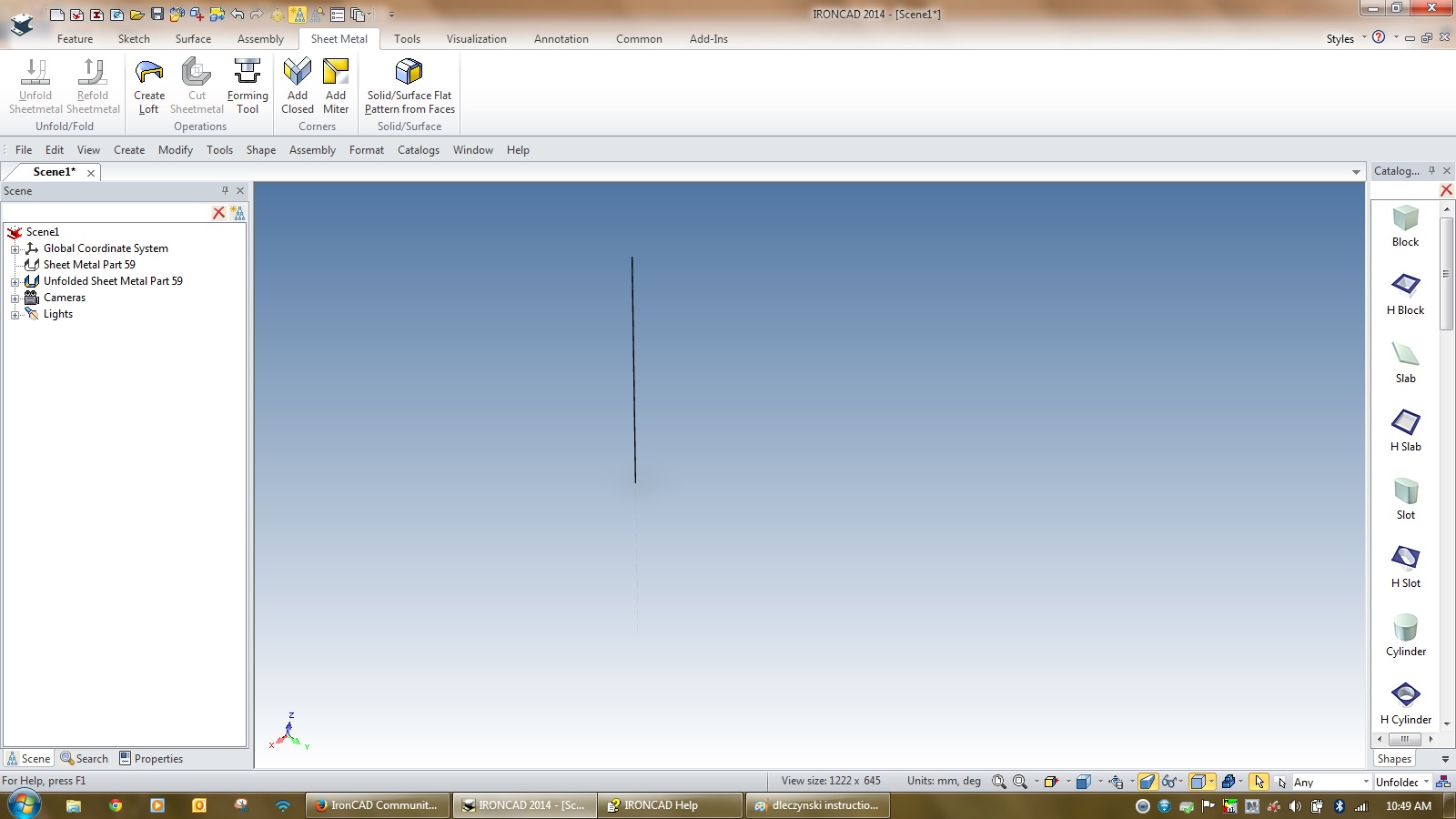
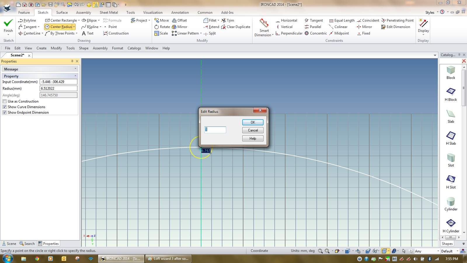
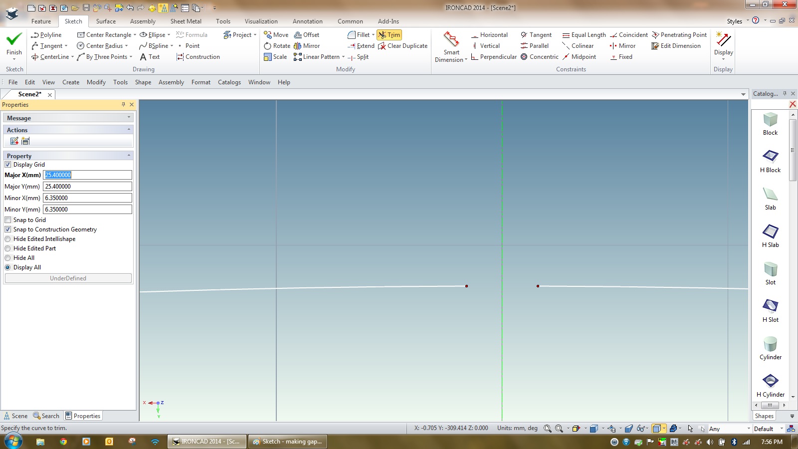
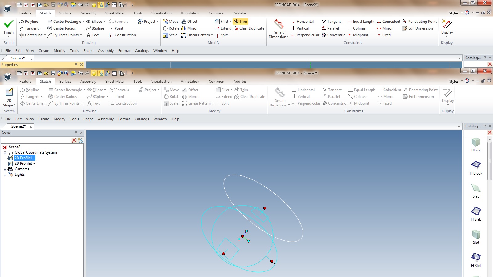
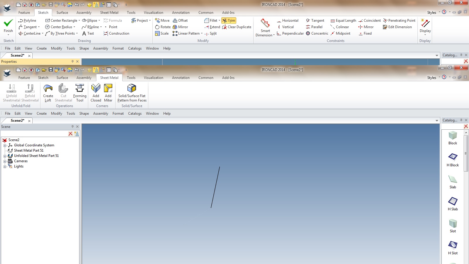
Thank you. I followed your instruction exactly. Unfortunately, when it came to the unfold, all I got was the line as shown below. So something's happening when I hit the unfold button. It maybe a setting I have wrong or one simple step during the loft build process, however I have now followed several sets of instructions and got the same 1 line result when pressing unfold.


-
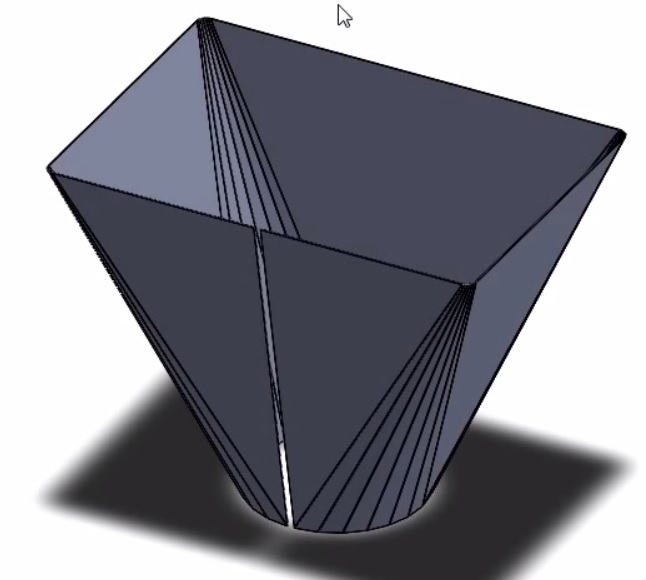
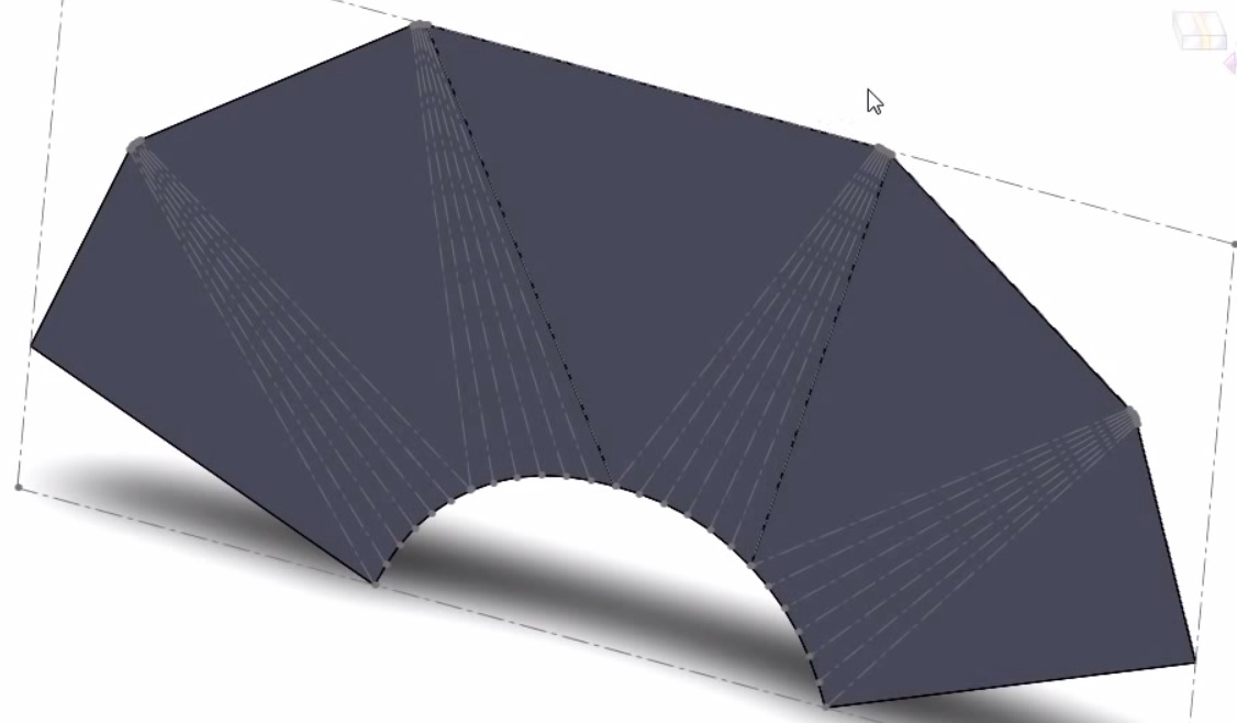
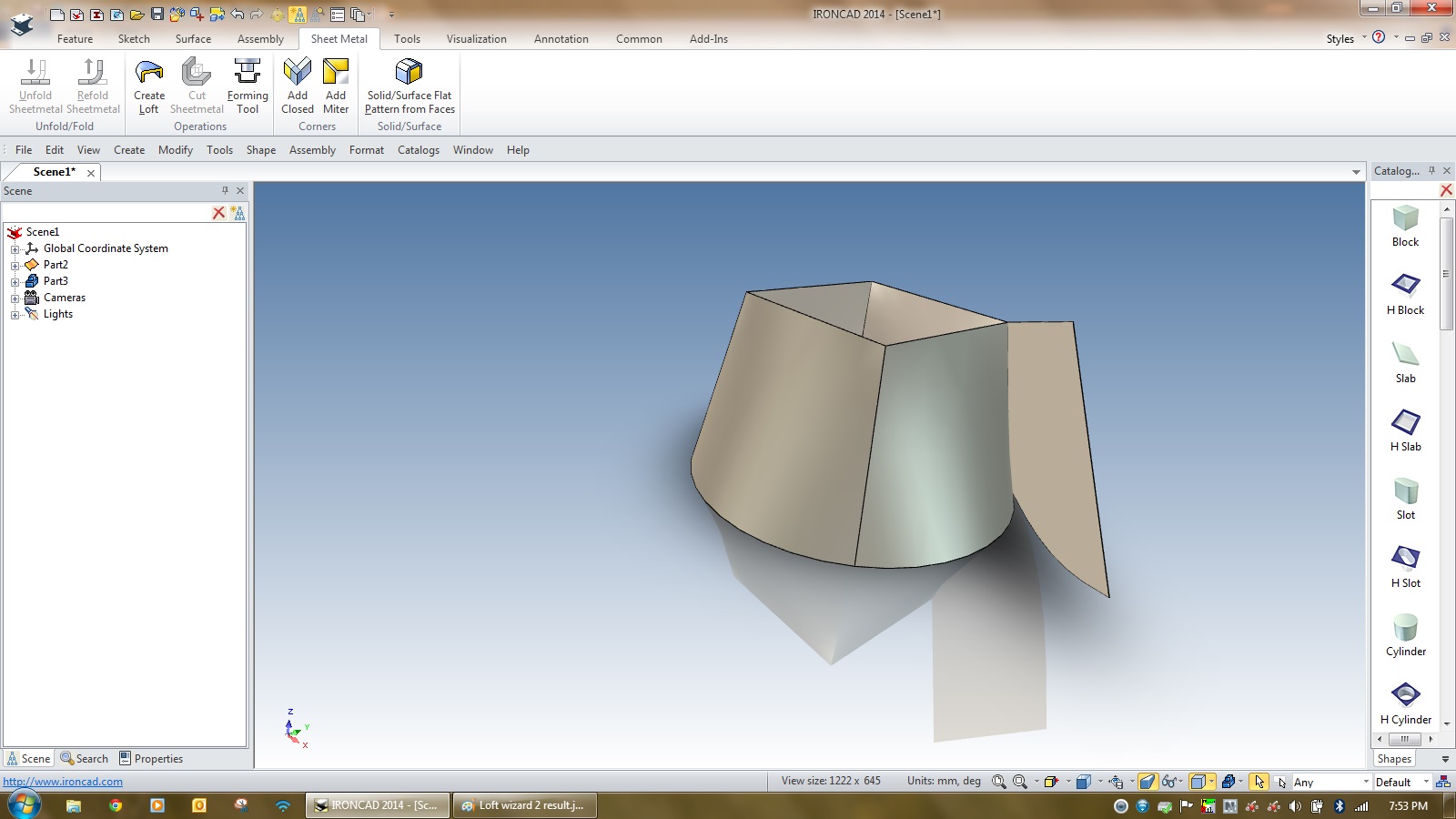
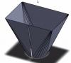
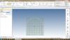
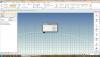
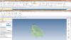
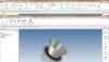
A good proportion of our products consist of sheet metal transitions; square to round symetrical, square to round offset centre, round to round symetrical, and round to round offset centres. Having spent the weekend going through IC lessons, I can't for the life of me get the lofted sheetmetal transistions and their developments ( unfold ) working properly. I'm screwing up, but do not know where. I bet it's a simple step I'm getting wrong or missing. Attached; 1) Transition of what I expect it to look like with all development folds where you'd expect them ( SWX lesson ) 2) The resultant development ( fold out ) 3) Using IC Loft wizard - various steps and the results ( lousy unfold out shape and development fold lines) 4) Steps using sketch, trimming a gap, copying to another plane, resize, loft and trial unfold - ends up just a line! The attached files should be in sequence of my explanation above HELP!


-
I'm new to 3d cad apart from some short but fruitful experience with sketchup and my son trying to get me to go with solidworks.
-
Being a newbie, I was plodding my way through the "Getting started guide". I had made a few mistakes in my progress and when I went back on them, they were just simple things I had got wrong or missed. However, creating the gears for the flywheel exercise had me stumped when on page 215, instruction 4.14.4 advised entering a formula for the expression next to 'Angle' as (360/Number)*radnumber. Nothing worked and I got real weird results. However after 1 hr continuous swearing after many re-draws, I realised the formula was in fact incorrect. It should have read "(360/Number)/radnumber" in other words division rather than multiplication!