HDEAR
-
Posts
1,021 -
Joined
-
Last visited
Content Type
Profiles
Forums
Blogs
Downloads
Articles
Gallery
Everything posted by HDEAR
-
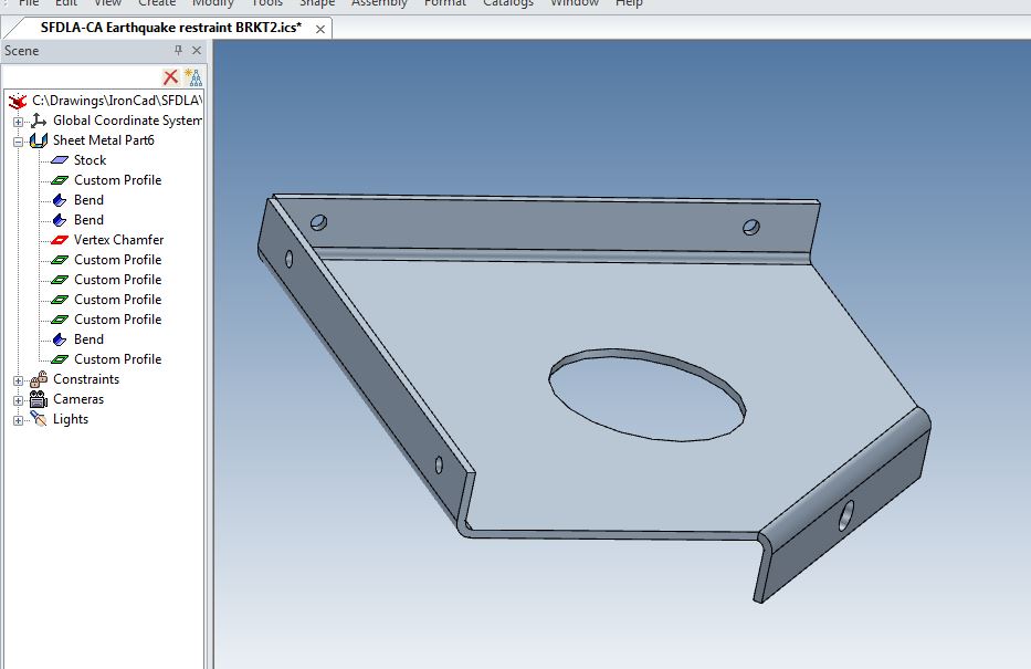
Thanks Steve, That looks reasonably quick to me, but I guess your time was taken finding out how to do it in the first place. Anyhow, for what it's worth, I tried to figure out what you did in conjunction with what I've recently learned from Jonas, and got the exercise down to about 15minutes ( hindsight is a wonderful teacher ) Attached pdf explains my process. You will see I struggled with the reliefs on the bends but once I figured out how to fix them ( measure error and then a bit of trial and error ) it was a snap. Anyhow, I learned a lot from your video, so once again, thanks. I think your method was better for the bend reliefs to work quicker. Bracket_model_to_draw.pdf
-
Grasshopper acknowledges The Master's teachings. "Many thanks" The enlightening points for me that I learned from Jonas' methods were; 1) You can edit the shape of a sheetmetal part by selecting the ,Sheet Metal Part xxx' in the Scene tree, expand, RMB on 'Stock' and select Edi cross section. 2) Custom profile is an extremely versatile tool which can be used to manipulate shapes around the outside of a part as well as inside( I ad previously thought that 'custom profile' acted purely like a hole in that its perimeter had to be within the bounds of the part - not so)
-
import sheet metal brep to sheetmetal ironcad
HDEAR replied to dleczynski's topic in Tips and Tricks
I can't do the bends or anything to the imported BREP -
import sheet metal brep to sheetmetal ironcad
HDEAR replied to dleczynski's topic in Tips and Tricks
You can get this to work? That's encouraging. I wonder what I am doing wrong then. Is it to do with the placement of the catalogue part onto the stock - is there some additional key-stroke that does not show in the video? I interpret the steps in the video as mentioned in previous post. Harley -
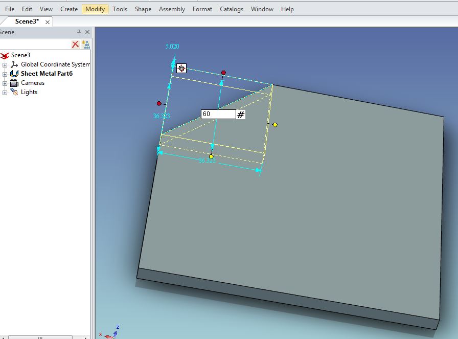
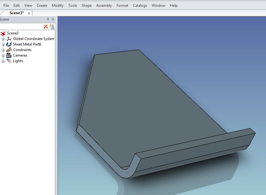
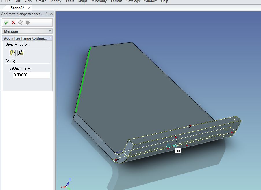
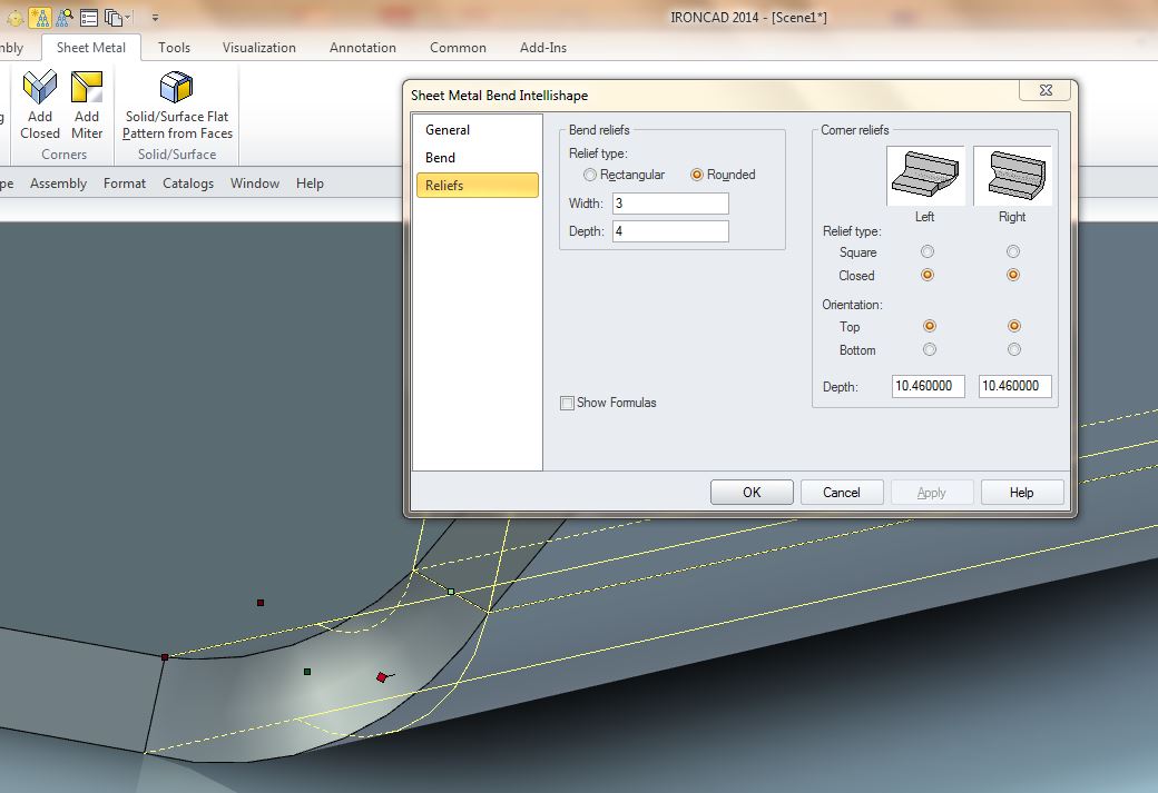
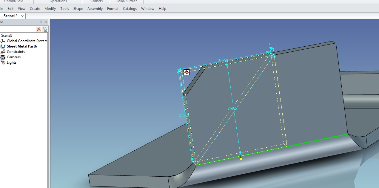
This may help, late, but better late than never; 1) Create the base plate, in this case 5mm plate 100 x 100 and create a vertex chamfer in one corner, say 60mm 2) Add a normal bend at opposite corner 3) Perform an "Add Mitre"using the opposing bend and place it on the vertex chamfer cut line 4) The tricky part. Select the bend at intellishape level, select relief mode and change the reliefs both to 'Closed' - 'Top' and the values must represent the inside radius of the bend, plus the material thickness PLUS whatever the hypotenuse of the K factor is for an right angle triangle- in this case K factor is .33, therefore the hypotenuse of a .33 right angle triangle ( two side equal ) would be 0.46. This example then makes the relief to be 10 ( 5 + 5 ) plus 0.46 5) Extend the bend higher than what the next vertex chamfer cuts will be and perform vertex chamfer on one side, using the bend line as finish point 6) Do the same on the other side 7) Kill the opposing bend 8) Unfold - result should be a perfectly square ( or oblong as the case may be ) piece of metal just like you'd have if you'd drawn a 45 degree line across the metal piece and stuck it in a press brake. Refer Jonas' method below, much simpler.


-
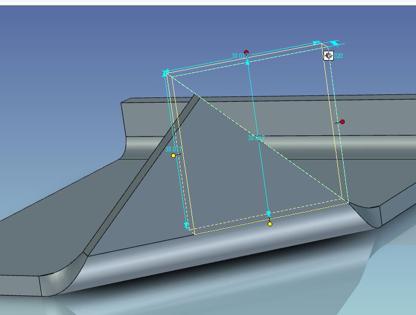
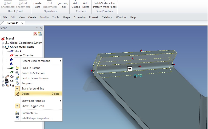
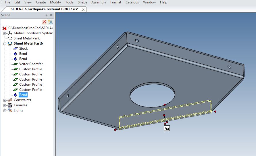
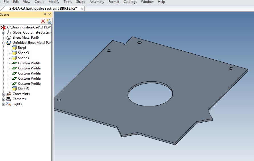
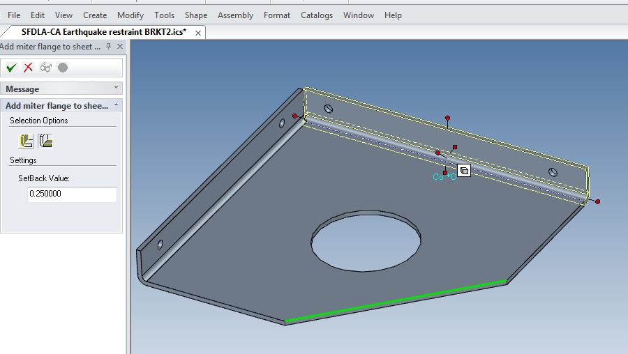
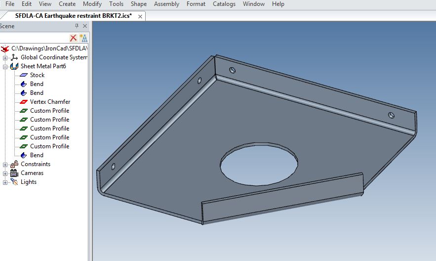
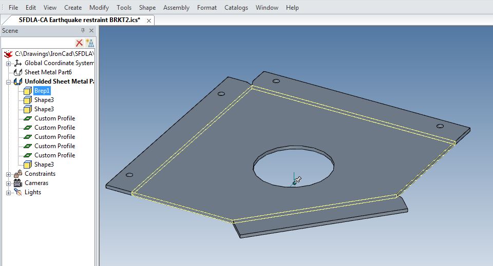
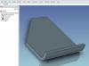
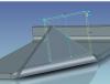
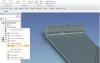
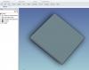
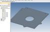
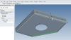
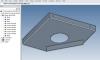
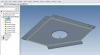
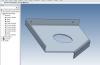
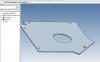
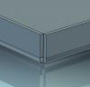
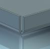
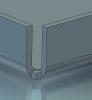
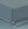
I got into grief trying to add a bend to a sheet metal vertex chamfer feature. Pic 1 - Shows the bracket with two bends and a vertex chamfer added Pic 2 - Add a standard bend Pic 3 - Unfold = undesired result! The square of the original material stock shows up !!! ???? Pic 4 - Instead, create a mitre corner feature and select the hypotenuse of the vertex chamfer feature where you want the bend to form Pic 5 - Bend created - NOTE! Make sure you do closed corners on the previous bends AFTER you add the mitre to the vertex chamfer, otherwise you'll get strange results Pic 6 - Unfolded ( if you're observant you'll see the odd result on the right hand side of the new bend because I performed the closed corners prior instead of after! ) Pic 7 - I actually now need the bend to go the other way, so I re-did the mitre and applied to the bottom edge Pic 8 - Unfold If there's a simpler way of doing this, I'm all ears. Oh, and if anyone could explain why 'Bend' created a problem with unfold, yet Mitre didn't, that would be great. Harley
-
import sheet metal brep to sheetmetal ironcad
HDEAR replied to dleczynski's topic in Tips and Tricks
I have tried to emulate what's been shown in this brisk video, but can't get the same result. It seems that the steps are; 1) Bring in sheetmetal stock and adjust thickness to match BREP thickness. ( it's not clear if the stock has to land flat onto the BREP ) 2) Drag BREP over to catalogue to placxe copy there. 3) Delete BREP in scene 4) Drag BREP ( left mouse click ) onto Stock 5 ) Suppress stock 6) BREP will now inherit stock propertise that will enable it to have standard sheetmetal features ( such as bend ) added to it. If that's what's meant to be done, what part of the magic am I missing? Ideas please? Harley -
Steve, how did you achieve that? I have tried to emulate what you describe here but have not been successful. Can you provide bullet point steps?
-
Come to NZ. You'd get Three Boys for that effort. http://www.threeboysbrewery.co.nz/
-
Here's my first attempt at a sheetmetal tip/lesson, in gratitude for the help I have had here from others. If I knew how to do a video, I would, but I don't so here is the pdf and the ics file. Harley Creating_a_two_piece_holding_frame_from_1mm_sheet_metal_complete_with_hem_and_mitred_corners.pdf CHF66_110.ics
-
Here are two pdfs of the video with actions translated into English for the Jog and the Gusset. Creating_a_jog_in_Ironcad_2014_without_IronPro.docx Creating_a_gusset_in_Ironcad_2014.docx
-
Thanks everyone. I appreciate the time you put into this. Harley
-
Just the ticket for the ROOs that come out of nowhere
-
Thanks Tom Handy stuff, especially if you're doing Boolean subtraction. Harley
-
I can't find either a jog or gusset tool in IC that can easily add joggs and gussets. Then again, I'm known to overlook the obvious What do you sheet metal guys do to get around this easily and quickly?


-
Yes it has thanks. I've managed to put out two new designs and have them produced by our contract sheet-metal fabricator. Even had to learn about producing drawings and saving them in .dwg as they only have autocad 2004 !!! On to the next challenge I guess...
-
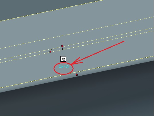
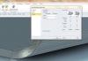
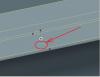
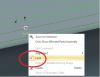
Thanks Mike for chimimg in and bringing up the awareness of the constraints. So much to learn and so little time I couldn't find the 'blue constraint' at the intellishape level of the bend however when I changed 'Options-Sheet metal-Constraints - Auto constrain' to off, it worked. Just to make sure I am doing this right, I left clicked on the bend twice to bring up the intellishape level ( yellow dotted lines ) but when I hovered over all the handles, none were blue, they were all yellow. Bet I'm doing something wrong or missing a point because I would like to be able to change auto constrain on the fly, rather than have it globally set for the whole scene parts. UPDATE! Solved it. The blue constraint appears under the shape control. I right clicked that and it come up with menu that did not mention 'Auto constraint', but had the option 'Lock'. Once I un-ticked 'Lock' I could do what you mentioned. Obviously this 'Lock' refers to the constraints. Pics below
-
Okay, it's becoming clear. I had trouble working out what 'rm menu' meant. Finally after an hour of searching, I came to realise rm = 'Right Mouse'....DOH!
-
Thanks Jonas. Not sure I 100% understand everything mentioned ( being a novice ) but still get a good idea. I will fiddle around with this and eventually get what your explaining I am sure. The reason I wanted the holes to move with the separate parts, even though they were 'matched' was to move or copy the part to another area of the scene to do some comparisons ( or unfold ). I like your videos, even the Swedish dialogue I can follow a wee bit.
-
Thanks so much Jonas. I have been working in sheetmetal for over 40 years now so making the calcs for bends and lengths is second nature. I guess I was feeling lazy seeing that in and out bends were a feature and theoretically could save a bit of time, but seeing they cause that much trouble I'm fine making the calcs or as you say finish the basic shape and work from there. The 'Auto-constrain bends" is active, I just checked. I'll do more experiment with shape handles as see what I can dream up. Again, so grateful for your input. Harley
-
Any ideas...anyone?
-
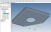
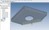
Inspired by the 'Assembly Feature' video found at http://www.ironcad.com/index.php/support/t...learning-center , I thought my 'picking a fastening ( in my caes a hex hank nut ) and drilling through the sheetmetal' problems were answered. To some extent they in fact are. First three pics show process which works fine. However, when I either move one or both the parts completely I have applied the 'HCylinder/drop as assembly feature/all assemblies under selected level', the hole disappears - refer 4th pic. Further, once I unfold either of the parts, the hole has also disappeared refer final pic I was kind of hoping that once applied, the hole would be sort of permanent in each of the features and if there was any movement of the actual placement of the hole in relation to the first feature it was placed on, the hole in the other part would move accordingly. I was expecting the holes to show up in each of the unfolds. Am I expecting too much of the feature as shown in that video do you think? Is there some point I am missing, or other method I could use that would help me achieve what I was hoping for? It sucks being a newbie to this at times. Any help/advice much appreciated and welcome - thanks. Harley


-
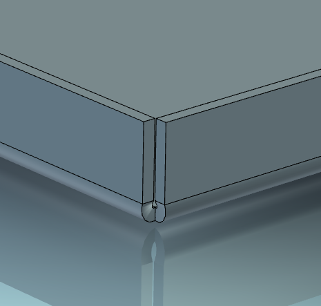
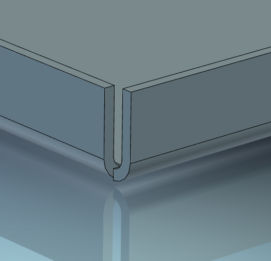
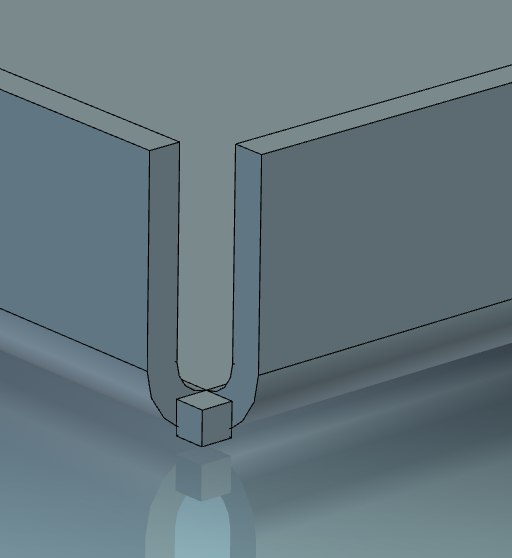
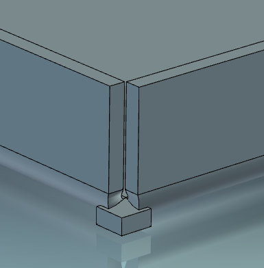
I get differing results using 'Sheetmetal Closed Corners' when I use 'Bends', 'In bends' and 'Out bends' 'Bend' works perfectly but often I would rather use 'In bend' or 'Out bend' depending on what type of sheetmetal construction I am working on,purely to save time having to make bend and material thickness allowance calculations. The following pictures describe the problem. First picture shows what result I get when using 'Bend', then closed corner. Happy camper with this one. Using 'In bend' and 'Out bend', once I perform the bends, one overlaps the other, so it needs to be brought back so that the indices match. This is where the problem seems to begin - refer second and third pics and you will see material left over from moving the bend. Then when I apply closed corners, there is material left in the corner which is not what would happen when making such a bend in reality. Is it possible I have to add some sort of relief before performing the move bend for in and Out bends? If that was the case, then wouldn't that defeat the convenience and purpose of using 'Closed Corners'? Any advice welcome, thanks - Harley
-
Thank you Jonas. Much appreciated.
-
Absolutely marvelous! Thanks a million. Hope I can return the favour some day.