HDEAR
-
Posts
1,021 -
Joined
-
Last visited
Content Type
Profiles
Forums
Blogs
Downloads
Articles
Gallery
Everything posted by HDEAR
-
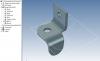
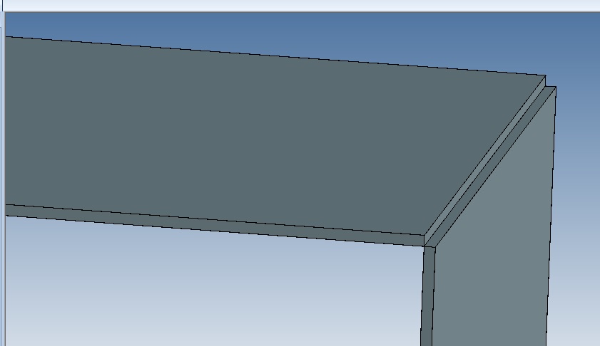
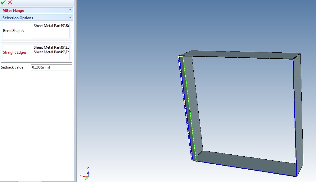
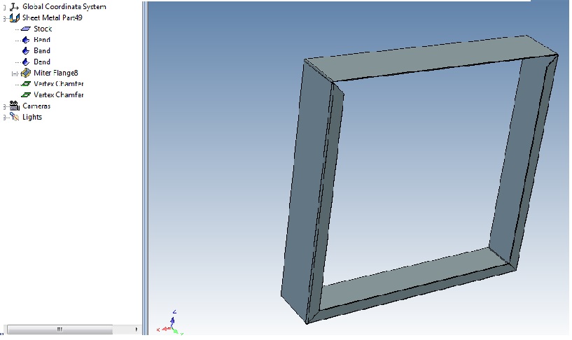
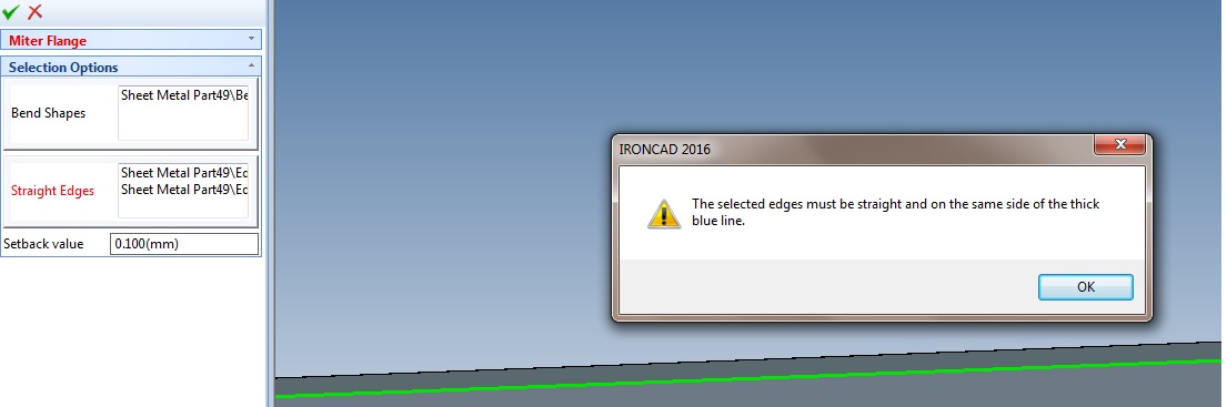
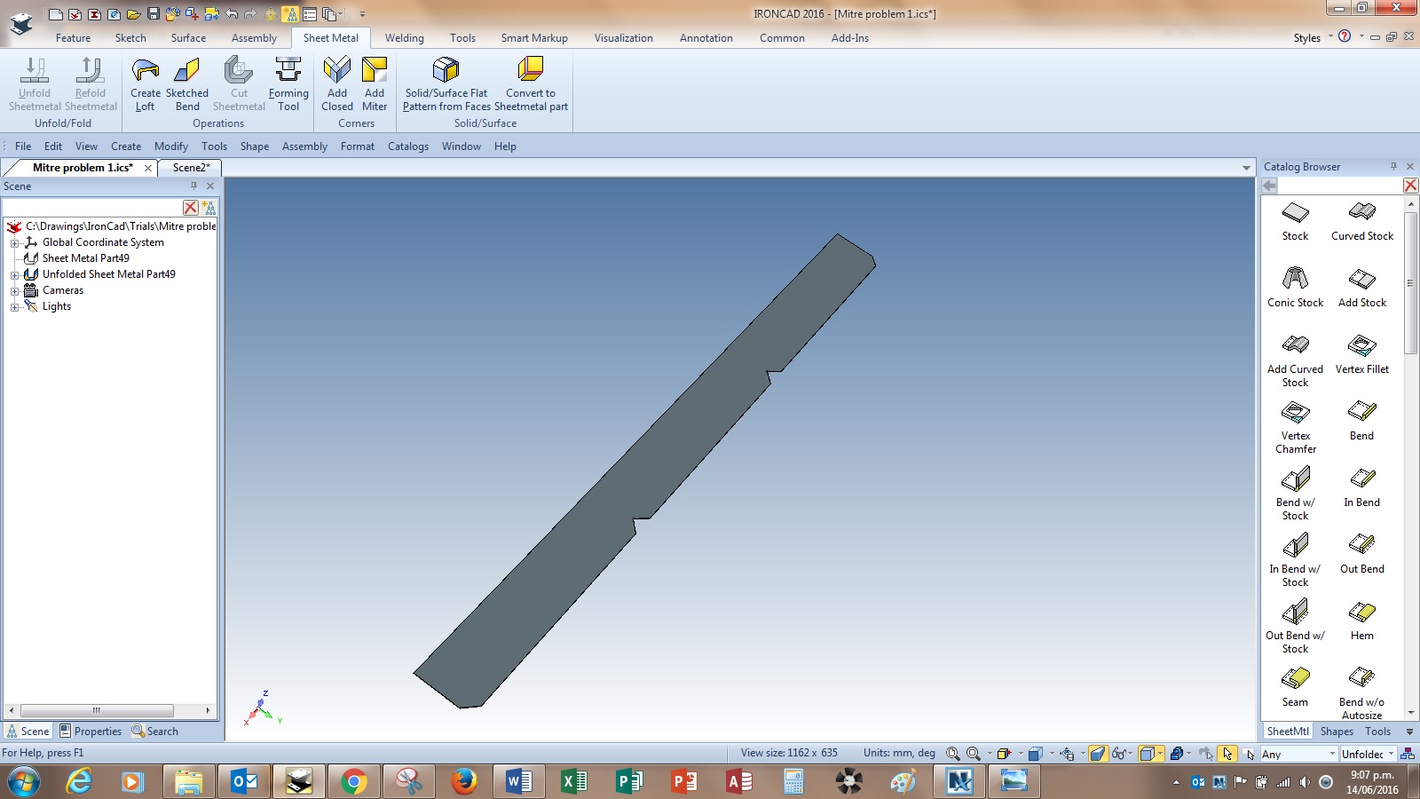
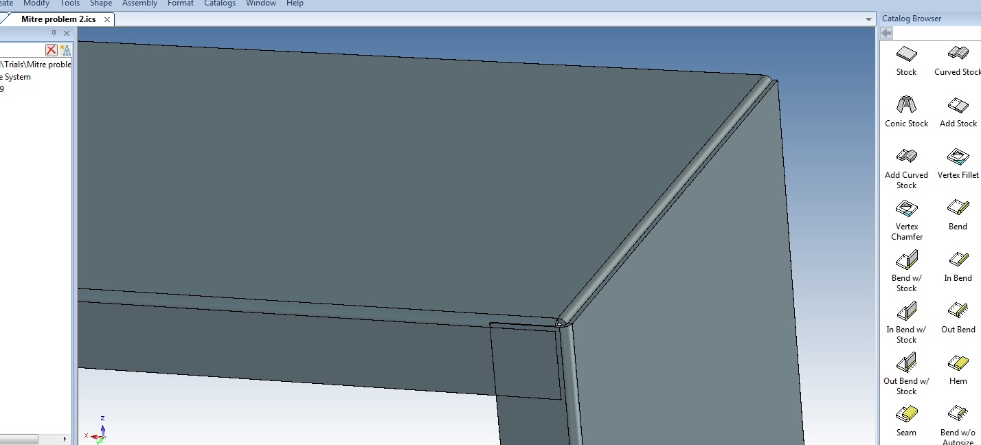
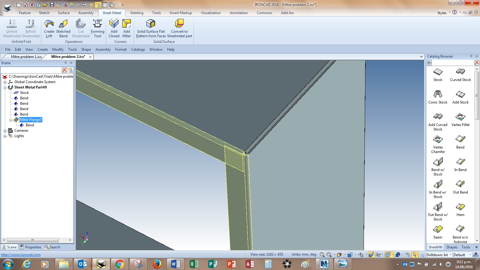
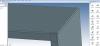
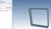
I recently updated to PU1. I was reasonably impressed with the new sheetmetal features as 90% of my work is in sheetmetal. I have struck problems with Add miter though and I wonder if it isn't buggy. I was making a 4 sided box out of 1.5mm st st 400 long that would have 25mm internal return flanges mitred at the corners - refer 'Miter Problem 1' which shows the design being an open butt corner for tig welding. The 1st bend was used to 'Add Mitre' ( refer 'Mitre prolem 0' ) but I could only get two sides to accept the mitre bend ( refer 'Miter problem 2' ) So I experimented getting around the problem by using 'Vertex chamfer' on the flat ends nearest the side that couldn't accept the 'Add Mitre' ( refer 'Miter problem 3 ) and the adding a sing bend on side 4 and modifying each end to suit ( a time consuming effort I might add ). Before adding the last bend I performed an unfold and got an unusual result ( refer 'Miter problem 4' ). The unfold resembles nothing like the 3D folded model would have you believe. So, I decided to tackle it another way by having a return bend on the last leg and use that for spot welding to the corner. The add mitre worked on all 4 sides except that it overlapped at the return fold end ( refer 'Miter problem 5' ). There was no way I could modify the straight ends using vertex chamfer ( refer Miter problem 6' ) as the the selection process won't allow that. Is this a bug or am I tackling this the wrong way? Mitre_problem_1.ics Mitre_problem_2.ics


-
I recently set up Product Update 1. I was reasonably impressed with the new sheet metal features as nearly 95% of my work is in sheetmetal. However I am struggling with the new Mitre Bend and I wonder if it isn't buggy. I tried making a 4 sided box with one set of corners butting together ( refer 'Miter problem 1' ) to accept a fillet weld. Material 1.5 st st. Then I wanted to add miter bends for internal returns of 25mm. Refer 'Mitre problem 0' I start the mitre bend feature but I can only select 2 other side, not 3 as in 'Mitre problem 2' So I think that to solve the problem, I'll fix it by doing a vertex chamfer on the straight ends of the mitres that worked and the add another bend and do the same. Refer 'miter problem 3' However, just before I added that other bend, I carried out an unfold and look what happened in 'Mitre problem 4'. Clearly that unfold shape resembles nothing like the 3D model. I then tried a new file with the design idea of having a return fold on the flat section to spot weld and then mitre - refer 'Miter problem 5'. All 4 mitered sides worked but there is an overlap where I want a mitre at the folded return end. now I could manually fix these two corners ( time consuming ) however I can't even carry out vertex chamfer mods on the two ends of the bends - refer 'Miter problem 6'. I used 'bends' command all the way through, not 'InBend' or 'OutBend' Is this a bug or am I tackling this the wrong way? Mitre_problem_1.ics Mitre_problem_2.ics


-
What programme do you guys use to make the videos that you place here on the forum? It seems to me there are a couple of programmes, not just one. The one I like has the cursor highlighted when pressed and indicates whether the right or left mouse button has been pressed or a combination of keys. Thanks
-
Working with Sheetmetal Fabricators WorkFlow?
HDEAR replied to tlehnhaeuser's topic in General Discussion
Hi Tom. A little late with the reply I guess and I am just echoing what most people have written. I'm a newbie to IronCad as you know but I've had extensive sheetmetal experience both in design and application. If I am using a new sheetmetal worker, I go to their shop, look at their equipment, discuss the capabilities and find out what formats they like to receive cad stuff in. I have found that most shops will tell you what K factors they work with, what minimum bend radii for various gauges and materials etc etc. I tray and pick a shop with good machinery and good operators. In nearly all cases they're wanting four things; 1) If an assembly of various parts, a 2D GA of the whole shebang. 2) 2D drawing of the part/s - dimensioned in finished form, i.e. not unfolded, 3) 1:1 metric dxf of unfolded part/s, with no fold lines or dimensions, and 4) Some Keyshot close up renders of anything clever or likely to be unclear. Result - no mistakes. They generally don't get that from their other clients. It keeps the price down too plus encourages good feedback from them. I also learn new tricks of the trade -
Is anyone else having trouble getting the views that you select from the scene when in .icd to actually show up on the drawing sheet? OK - forget this. Joseph suggested there was a regsitry bug, I removed IC2016 and re-installed - it seems to have fixed the problem.
-
It's probably very obvious and written in some instruction somewhere but how do you go about changing a name for an .ics file that has .icd files attached/linked to it. I tried the 'save as' on a scene with both the .ics and associated .icd files open but the .icd files stayed linked to the original .ics file. When I look at the properties on any of the 'icd views, the old linked .ics file shows but there seems nowhere to be able to renew the link. Forget it - I found it DOH!
-
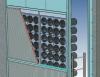
OK, I disposed of the linked pattern vanes and simply used Triball/copy of the required no of vanes across the louvre and it worked. 'Copy - Link' pattern didn't work for some reason. Precise mode was checked as well. The frame and louvres were one assembly. Anyhow here are the results in Keyshot, and for the small amount of time it will take to change the other louvres, it's worth it. Thanks for your help guys.


-
Thanks. I tried that but because the louvre is an assembly of 4 outer frame extrusions and about 100 vane extrusions, 'Precise' only sections the outer frame and not the vanes. I used 'Block' to see what effect that would have. It sectioned the outer frame but not the vanes. Perhaps it's how I make the assembly of the louvre? All the parts that make up the louvre are bought into the one assembly - there are no sub-assemblies. The vanes have been produced by linear pattern off one vane.
-
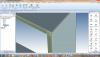
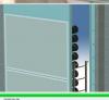
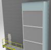
How do you go about getting a part you have sectioned in .ics to show the sectioning effect in either Ironcad render or Keyshot? Shot one is of the sectioned part in the scene. The sectioned intake louvre is shown and the right hand housing panel is hidden. Second shot done in IronCad visualisation render. The sectioned louvre does not show the sectioned effect, but the hidden pane remains hidden. Third shot is render in Keyshot. The sectional effect and the 'hidden panel' don't show their effect. Now I do know that to hide a part in a Keyshot render, you suppress the part in the scene or in the Keyshot item selection menu so that's no biggie. I'd like to have the part I sectioned, show as a section in IC Render and Keyshot render. Help please?
-
Thanks Kevin. Yes I used that way of loading the files onto my iPad which worked seamlessly but the problem was when I opened Compose on iPad, I could not locate the files. B'Ludin pointed out I need to export it in .icsw format, which I wasn't aware I had to do before.
-
Nope - I'm an old fart, things like that don't come to my attention...easily Thanks for the tip.
-
I loaded Compose app on my iPad and used itunes to 'Add files' to the app. I cannot find out how I now access those files to load. I note on the website it mentions "On the iPad, you can access the email or DropBox account from the Apple device and can select to load into IRONCAD COMPOSE" Does this mean that using email or dropbox is the only way to load files and using the itunes transfer ofr files form PC/Laptop to the Compose App won't allow you to load that file?
-
Problem exporting *.icd drawings to dxf and dwg
HDEAR replied to HDEAR's topic in General Discussion
OK, I un-installed then re-installed IronCad and the problem seems to be fixed. One thing I did notice however was that when I used the 'Recent documents' history tab to open the offending files, I got the problem. If I opened the file by using 'File --> Open, then no problem. Thanks to Kevin for swift response and also to Joseph for re-installation support -
Problem exporting *.icd drawings to dxf and dwg
HDEAR replied to HDEAR's topic in General Discussion
Thanks. I tried on older saved files with the same result. Files sent to Kevin -
Problem exporting *.icd drawings to dxf and dwg
HDEAR replied to HDEAR's topic in General Discussion
Will do. Now here's a weird thing. I emailed myself the drawing from home to the office last night and lo and behold the copy I emailed can be exported no problem, but the file on my hard drive cannot. Files being emailed to you now. -
Is anyone else having problems exporting *.icd files to dxf and dwg? Here is a simple drawing I am trying to export and it comes up with error. I tried various versions of dxf ( 2004, 2013 etc ) but still the same problem. In addition, I tried exporting icd files I successfully exported before the patch but get the same error. What's going wrong do you think?


-
Yeah, that's on my request list to management for them to shell out for what I consider is a good investment. Thanks others for your replies. Malcolm - PM message for you on GrabCad
-
I went to issue an .ics drawing to a subcontractor who has installed Compose so he can explore my drawings if need to to ensure they interpret our intention correctly. The problem is my drawing has about ten linked files for various sheetmetal parts. I have tried using all the various option that come up under 'Save as' to provide him just one file that doesn't require a search for the linked parts, therefore used 'Do not process linked parts'. However, when he opens up that file, it won't open due to the drawing looking for the linked parts. The option of 'copy all linked files to the new assembly file directory' works, and allows him to open the file. However, I was really not wanting to have all the linked files needing to be copied in order for it to work. Is there another way perhaps to provide him just one .ics drawing that he can open with Compose and not require all the linked files to be provided as well? I couldn't find much help on this topic using the F1 key either.
-
import sheet metal brep to sheetmetal ironcad
HDEAR replied to dleczynski's topic in Tips and Tricks
Sweet - works for me now with that one tiny but ever so important extra step . Thanks ever so much Eric and dleczynski. -
Thanks - I emailed the drawing to you. I appreciate your swift response. Harley
-
How do you get a DWG file created in Autocad, imported into CAXA, that contains the model in 'Model Space' and the 'Paper space' ( template and dimensions ), to print both Model Space and Paper space together? The file I have imported and modified, will print what's in paper space but doesn not include what is in model space. Any ideas what I've missed setting up please? Thanks Harley


-
Well, for some reason I do not completely understand, I am getting the bent bracket to work about 8 time out of ten. I noticed in your file that your bend radius had changed from the minimum standard on the parts property ( 1.5mm ) to 1.6mm. I guess you do that to prevent conficts on the bend vertices when you were altering the stock size dimensions. When I added bends sometimes, then immediately saved and closed the file, it come up with a conflict on the bends which I chose to fix as per the dialogue box when I re-opened it. This seemed to have an effect on the finished article. Also pasting the sketch when editing the custom profile prvde tricky as often the sketch would be the opposite hand of where I wanted it to be. Fiddling around too often meant the finsihed article had problems. Anyhow, I seem to be getting it right and now the next challenge is to see if your method will somehow take two bends, for instance a stamped blank with straight sides, folded in two areas to produce a handle. I can get the right shape when unfolded, but when I refold, the sketch shape only takes on the first bend. Files attached Harley Yet_Another_HD_bent_bracket.ics

-
Thanks. Yes, I have since learned this is a better way to go. Being a newbie, I wasn't aware that tool ( 'Edit cross-Section' ) could be used to shape sheet-metal when I posted that so now I have to suffer some embarrassment Live and learn Harley
-
Thanks - I am betting it's a setting or something like that. May be similar to the problem I was having with dleczynski's lesson on making sheetmetal from BREP files - he got it working, so did others but I couldn't Cheers Harley
-
Thanks - your video was very helpful. I used your method Steve and had a bit of trouble, no doubt something I missed or did wrong. First, the copy of the 2D profile, when pasted, was quite a way off where it should have landed and was also 90 degrees out. When I deleted the Custom Profile hole ( I used to start the profile off ) and finished the edit, I got no result. I then found that the profile was about 1.5mm higher than the folded stock face and once I dropped the Custom Profile onto the stock face using triball, one of the tabs worked ( accepted shape ) and the other one didn't. Yet when I unfolded, I had the correct unfold shape. Something real odd going on here. Sketches and the file attached if anyone can show where I screwed up. Thanks Harley Additional edit - I tried redoing the above but I couldn't even get one of the bends to accept the profile shape - ics Svan Bracket 3 drawing attached Svan_bracket_2.ics Svan_bracket_3.ics Svan_bracket_4.ics