


HDEAR
-
Posts
1,027 -
Joined
-
Last visited
Content Type
Profiles
Forums
Blogs
Downloads
Articles
Gallery
Posts posted by HDEAR
-
-
Thanks Malcolm, that was extremely helpful.
-
Thanks Malcolm. I sent you the file. Looks like it was dimensioned in model space.
-
Hi folks,
I have been given a dimensioned detail DWG drawing which has come in as a 1:1 model.
I need to be able to put this onto our client's A1 drawing sheet ( Layout ).What's the best way to go about this so the drawing and dimensions scale down to the layout sheet?
Thanks in anticipation.
Harley
-
On 7/22/2023 at 4:06 AM, Bertrand Kim said:
Finally, that window just got even messier.
Here ya go Kim, this will get rid of the mess.

-
 1
1
-
-
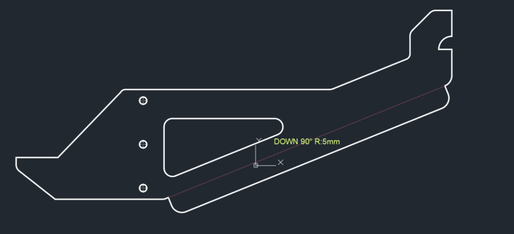
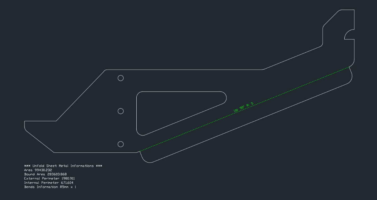
If I unfold, to 1:1 view in CAXA draft and export as DXF, the result is clean of information ( apart from bend info )
Seems the problem is with ICMECH package.
-
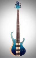
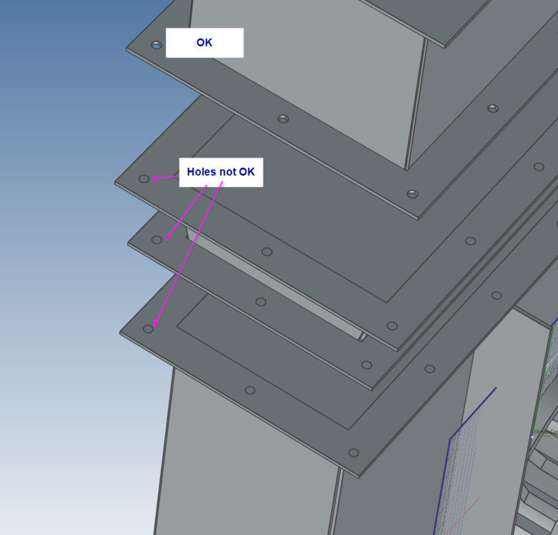
OK, I am getting pretty much the same as you Sarath.
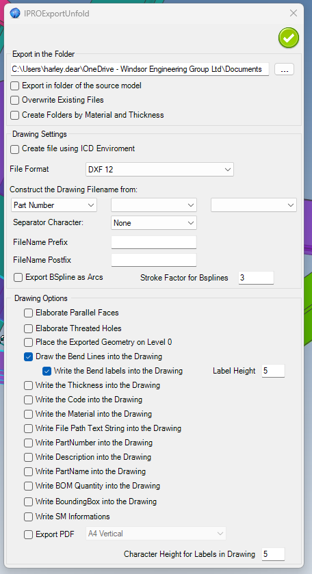
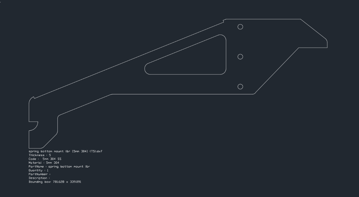
If I do Unfold Export to DXF with the settings as per below ( only requesting bend lines and un-checking write SM informations ) I still get some info as you see on the second DXF snip below.
When I use ICMECH Tool face to DXF, I get the whole 9 yards! ( first DXF snip below )

-
Hi Sarath. Post the ics part here. I'll try it on my ICUtils
-
7 hours ago, James McEwen said:
Thank you... .. sorry, re checking the dimbaseline.... worked. I knew I would feel dumb after seeing this solution.... haha. Cheers
Don't worry James - welcome to the club with a big membership

-
1
-
-
Thanks for the offer Dariusz. Kevin came back to say there was a bug in the translator.
Meanwhile I have sent you the files to see what you come up with.Many thanks,
Harley
Ooops - getting this
-
Oh, that easy huh! Thanks Malcolm

-
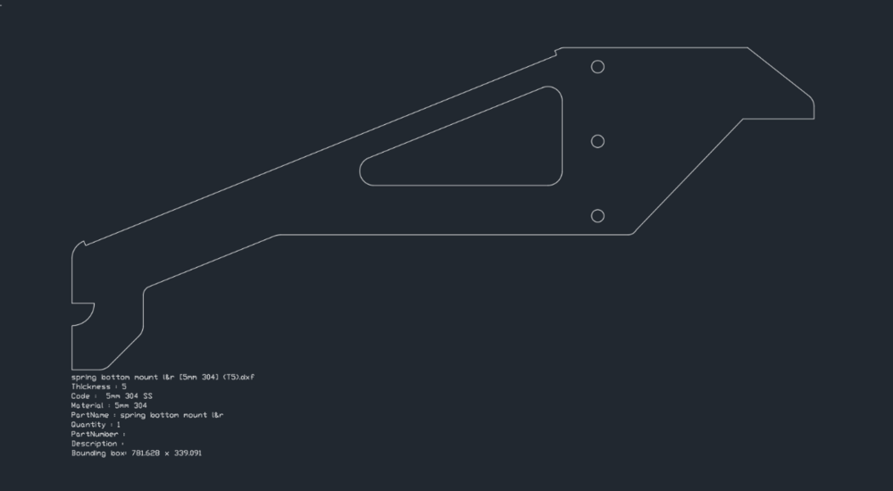
Hi all,
I can't find the control to disable the information fields coming up under the cross hair cursor like below.
I actually don't mind them, but they make moving the cross-hair around the screen quite jerky and slower.Thanks
-
1 hour ago, dleczynski said:
switch kernel to ACIS next import again?
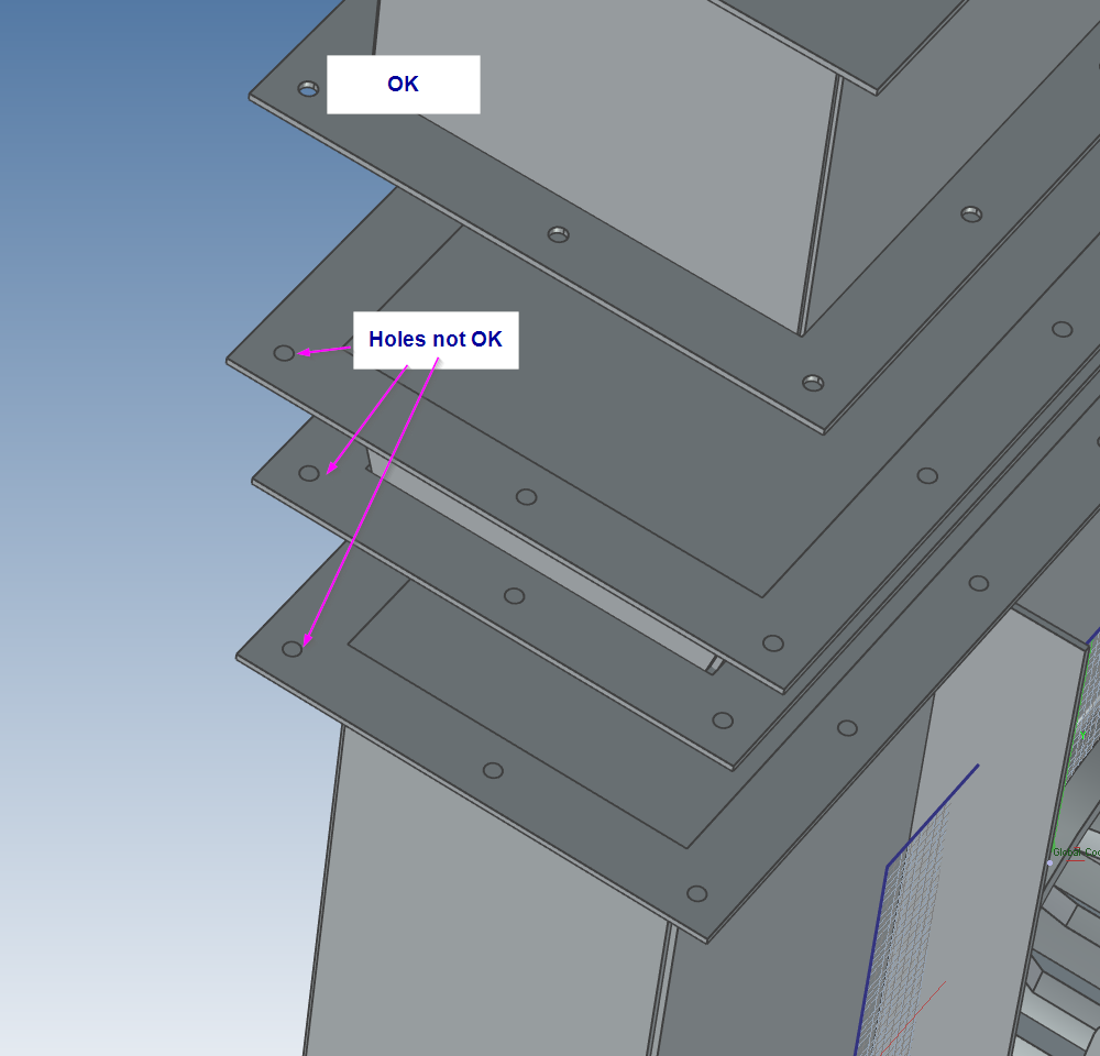
Thanks Dariusz. It works slightly better, BUT, there are still problems with holes, cut-outs etc
Plus when imported in ACIS, the assemblies in relation to each other are skewiff.
-
File sent Kevin.
-
Hi all,
I often get STP files coming in with surfaces missing. They're a PITA to fix.
I tried Surface-->Patch surface - that didn't work well.
Is there a simple quick way to fix these so they're solid?
-
Thanks Kevin,
Does that work in CAXA?
Cheers - Harley
-
9 hours ago, IronKevin said:
Bug filed.
QA 77659
Thanks Kevin.
-
Hi all,
The video explains the problem.
Harley
-
-
Hi Kevin,
You said you'd update this when IC2023 came out with some more new tools. Have you had a chance to do this yet
") ?
?
Harley
-
-
-
-
Hi all,
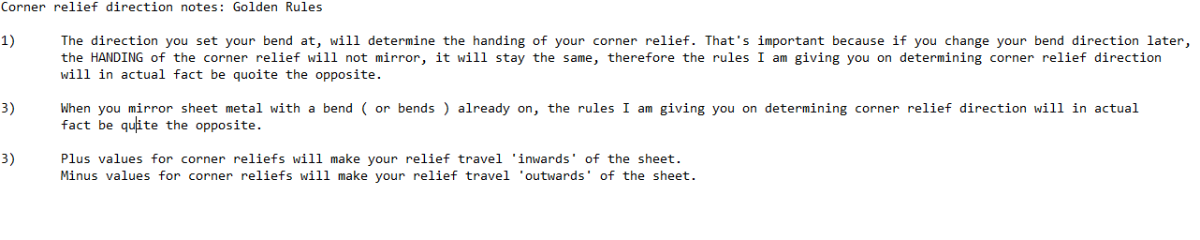
Further to my previous videos about working out left or right for corner reliefs, I decided to show you how I go about determining corner relief values on two ( or more ) sheet metal plates requiring internal or external mitred flanges.
There are 4 videos, so it pays to look at them in sequence.
I'm new at doing videos so take it easy on me won't you

-
 1
1
-
1
-
-
NOTE! The earlier video I made, had a major mistake. This has now been corrected ( noted May 22 20:24 GMT )
Here is a tip for those of you wanting to know which bend is affected when making closed reliefs.NOTE! The text 'Left' and 'Right' is only shown here to demonstrate which side is affected. Obviously you'd never put these texts on your actual model,
In addition, Malcolm has kindly lent me his handy ICS file which shows bend directions and 'look-at faces' to share with you.
Sheet Metal - Bend Corner Reliefs - Look At Face - 20230522.ics
-
3
-
1
-


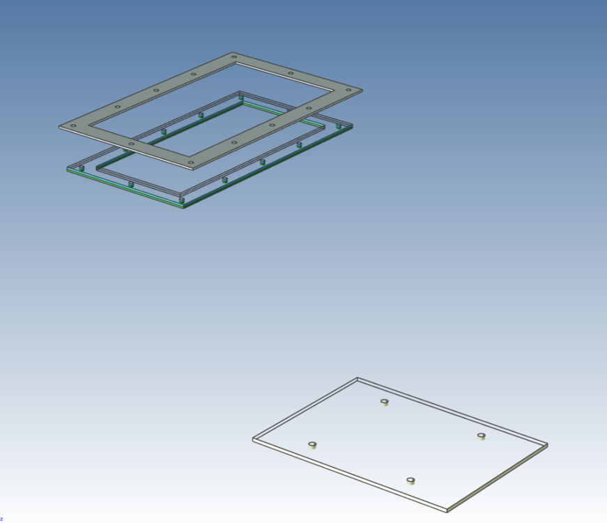
Mitre of seperate units
in General Discussion
Posted · Edited by HDEAR
OK, here's how I would normally do it. Because you can't mitre individual sheets, you have to know how to manipulate the bend reliefs. Once you get your head around that then it becomes relatively easy to set up a mitred feature.
So here's a video, sorry it's a bit jerky and I made some blues ( like not positioning the end bends properly at the start ) but you get the picture.
To make a mitred box like this, it would take me about 5 minutes tops ( without interruptions ). I never use out or in bends - I just make my own calcs and use smooth bends.
Note that to change width of ends, the mitered top bends will not follow the stock width change BUT it's just a matter of setting that underneath bend length to suit once that's done.
Enjoy
600x400x300 mitred box.ics
Mitred box instructions.txt