HDEAR
-
Posts
1,021 -
Joined
-
Last visited
Content Type
Profiles
Forums
Blogs
Downloads
Articles
Gallery
Everything posted by HDEAR
-
I don't know if this will help, but I recall asking the same question in 2014. Attached is what I kept as a reference. It's a bit of a mission to do the gusset though. Creating_a_gusset_in_Ironcad_2014.pdf Jog_and_gussett_lesson.mp4
-
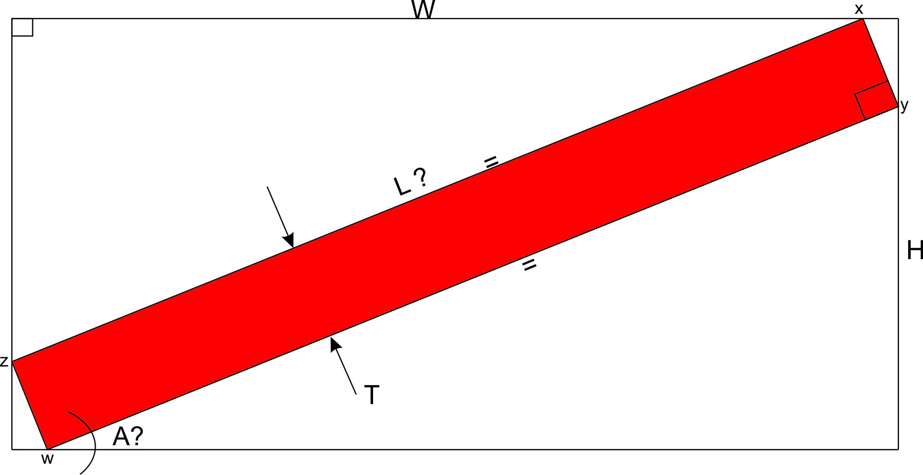
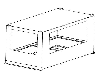
I have asked my 'space cadet' son to come up with a formula to work this out mathematically, but I was wondering how I can draw the following in 2D in a scene and then extrude. I need to fit blocks of a known thickness across two opposing corners of a rectangular hole. The rules are that all points W, X, Y and Z of the red block must touch the edges of the rectangular hole. I have three known quantities; W ( width of hole e.g. 700mm ) H ( height of hole e.g. 356.25mm ) T ( thickness of material 55mm ) How do I go about drawing this in 2D sketch in the Scene? Obviously I need to restrain points and offset the block's side L ( which I don't know what length it is ) but I don't know how to go about this. Any ideas, videos ? Thanks

-
I can't remember why either! I guess it was when I was screwing around trying to find the best way to design the overall end of the cabinet and deleted the stock for some reason. It all started to go pear shape when I modified the reliefs to closed. Now that's something I didn't check - the setback - which I normally have at ( say ) 0.2mm in real life. Yes please, a video on how you create that would be nice.
-
Thanks - yes that seems to be the problem; "parts that do not unfold correctly you can see from the structure that it is being caused by the user having bend geometry on other" Is there literature or instruction manuals/videos that cover this problem? It seems that there are many little tricks when it comes to IC sheet-metal and it would be good to have a comprehensive manual backed up by video. I've been working in IC sheet-metal now for 3 years yet there are still pitfalls that seem to trip me up. I am sure other people experience this too.
-
So are you saying it's a bug in the programme?
-
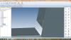
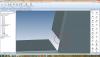
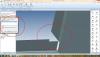
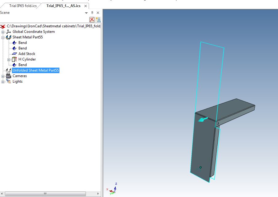
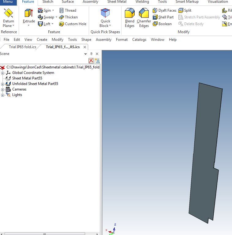
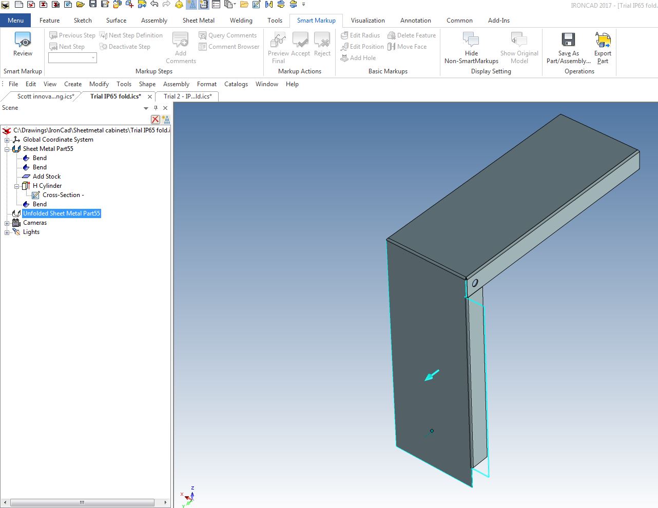
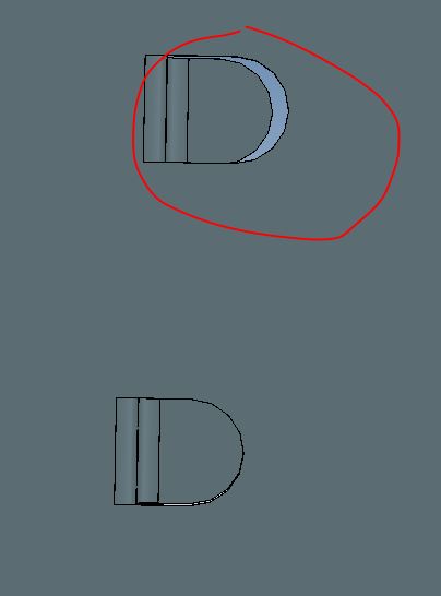
Thanks, but that didn't quote work when I opened it. One fold is still completely missing. Refer 1st attachment - you see the suppressed unfold against the folded item. 2nd attachment shows the part unfolded. 3rd and 4th attachments show the unfold of the model I made, which took many attempts to finally got the item to unfold correctly and include all features. ICS file attached shows all 3 models - my first one that didn't unfold, your one and the one I had to work over several times. Clearly something is wrong when I have to stage several attempts to get it the item to unfold with all the correct details - either a bug in the programme or in my settings - I can't work out which it is. Trial_2___IP65_fold.ics
-
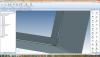
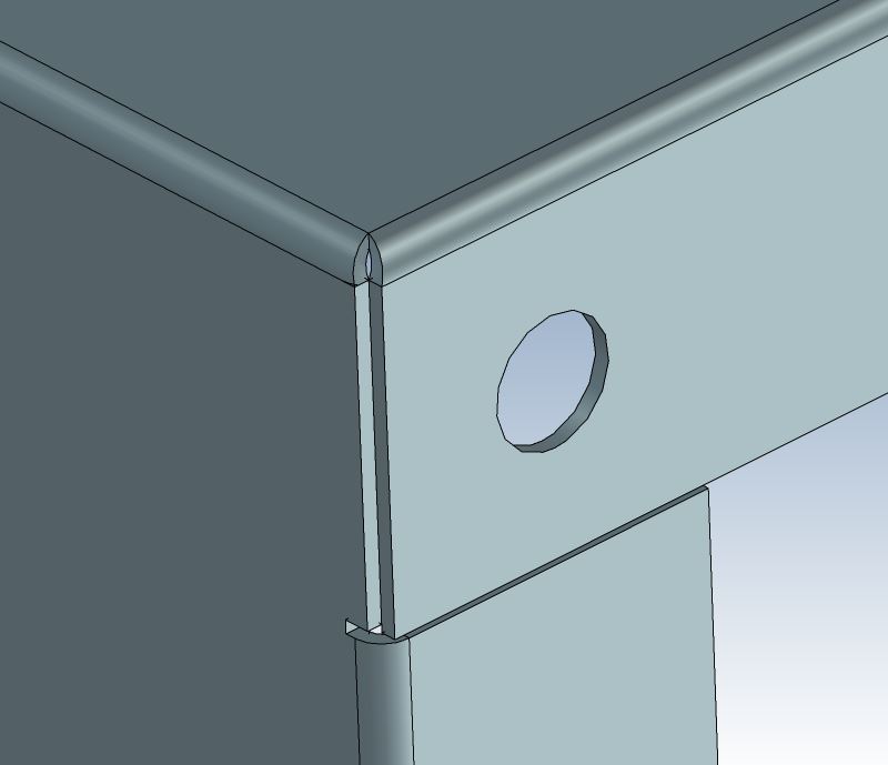
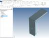
I have been having intermittent trouble with unfold in sheet metal since product update#1 Here's a typical example. Refer first attachment - I have created this corner detail using stock, bends, closed corner reliefs etc. When I unfold the item, only part of it turns into the development. I have had to start doing one bend at a time and unfolding just to make progress. Sometimes just deleting the bend and starting again works, sometimes not. A mixture of add stock or add stock with bend sometimes works, sometimes doesn't. Trial file shows problem. Trial 2 file shows progress Trial_IP65_fold.ics Trial_2___IP65_fold.ics
-
Thank you Kevin. Much appreciated
-
Hi all, is there a way to add/insert a jpg ( photo in this instance ) to .icd drawings? Thanks
-
Perfect - thanks.
-
A weird problem exists in a sheet-metal component drawing. I have 6 reliefs clearly detailed in the 3D scene, and there are two sets of bends that share a bend line between two bends. In 3D the reliefs show. In unfold only one relief along the shared bend line shows up and so getting a dxf file from this is awkward. Both 'unfold' in the 3D scene adn Export to DXF in ICMECH give the same problem. I bet it's something to do with how I have set it up but I cannot work out what it is. Anyone? Relief_problem_prefilter_plate.ics


-
I thought so. I guess I'm expecting a bit too much for IronCad to automatically work out the amount of deformity due to stretch and draw when punching as there are so many factors to consider. Even making the calculation by hand is daunting.
-
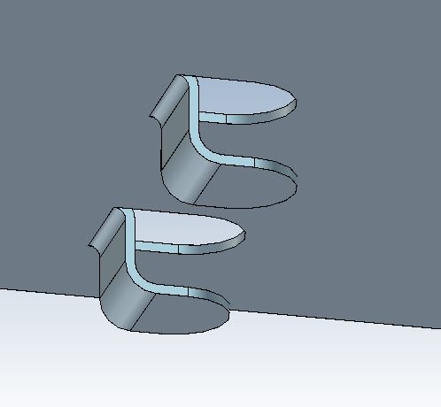
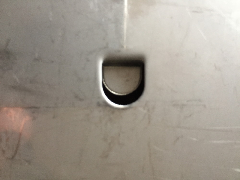
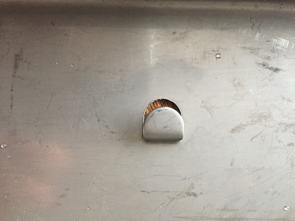
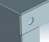
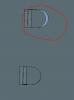
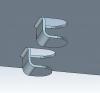
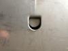
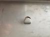
I have created a sheet metal punch in IC based on an existing tool. The punch works quite impressively, but the problem I have is that the cutout in the base sheet metal is exactly that of the punched part - which is punched down 8mm from the surface with a bent tab at the bottom. In reality, when you look direct onto the base plate, the cutout is about 1.5mm longer than the end of the tab looking in plan ( top ) view. You will see by the photos of the actual punching done on 0.9mm st st what I mean. The only way I have been able to mimic reality is to create a hollow slot, modify it and make the base plate punch that extra 1.5mm - see the first pdf, top slot circled in red. Is there a way to either create the punch so it reflects reality or is there a tool that available that I am unaware of to do this just in one swoop? I hope this all makes sense. Harley Edit: I altered the punch profile ( refer clip punch modified.ics ) which sort of works but it's after the fact ( having made the punch already ). It would be nice for IC to have pre-calculated that somehow when creating the punch with the forming tool - or is there part of the forming tool I could have used? Clip_punch.ics Clip_punch_modified.ics
-
I agree with Mike. Close to 100% of the work I do with IronCad involves sheet metal. There will be anywhere between 2 to 30 sheet metal parts, maybe more, for any one project I design and sell. I create a GA of the whole assembly and if it's complex, then some sub-assemblies with key dimensional placement of parts relative to the main structure. Then I create one drawing sheet for each part. Sounds more than obvious, but the hardest lesson I had to learn actually was how to efficiently name the parts and reference the GA and sub-assemblies to the individual parts. I also create 1:1 dxf unfolded drawings to send to our sub-contractor and again, consistency in naming the parts was essential. Plenty of 3D isometric sketches with 'detail' views help as I find there are less and less skilled sheet-metal workers around these days and you have to paint pictures for them to avoid mistakes.
-
Aha! Thanks Kevin...so simple and staring me in the face
-
There seems to be a difference in results of shaded rendered objects in .icd when printing or exporting to a .pdf file. If I use something like 'Cute PDF' as a printer, I get a nice shaded render print out just like on the .icd file when open. However, the line definitions for this method aren't 100% and are better when using 'Export ---> pdf' The problem however is that the nice shaded rendering ( particularly when I use colours in sectional views ) disappears when using Export . Is there a setting I am missing when 'exporting' that will fix this? BTW I have tried the various 'Default view creation modes' and quality settings - I still get an opaque ( not rendered ) object in the pdf when printed.


-
PERFECT! Thanks - so eeeeeeasy
-
Thanks Jonas, I only took IC2016 off because I thought it would be redundant now I had 2017 working. What's the best way to re-install 2017? Should I do a complete windows type uninstall and then re-install it again, or should I just run install without uninstalling?
-
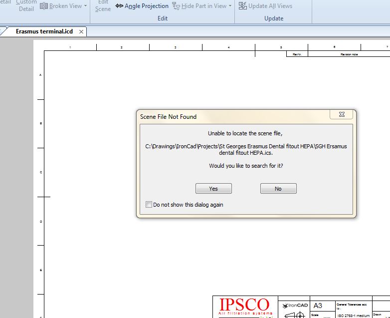
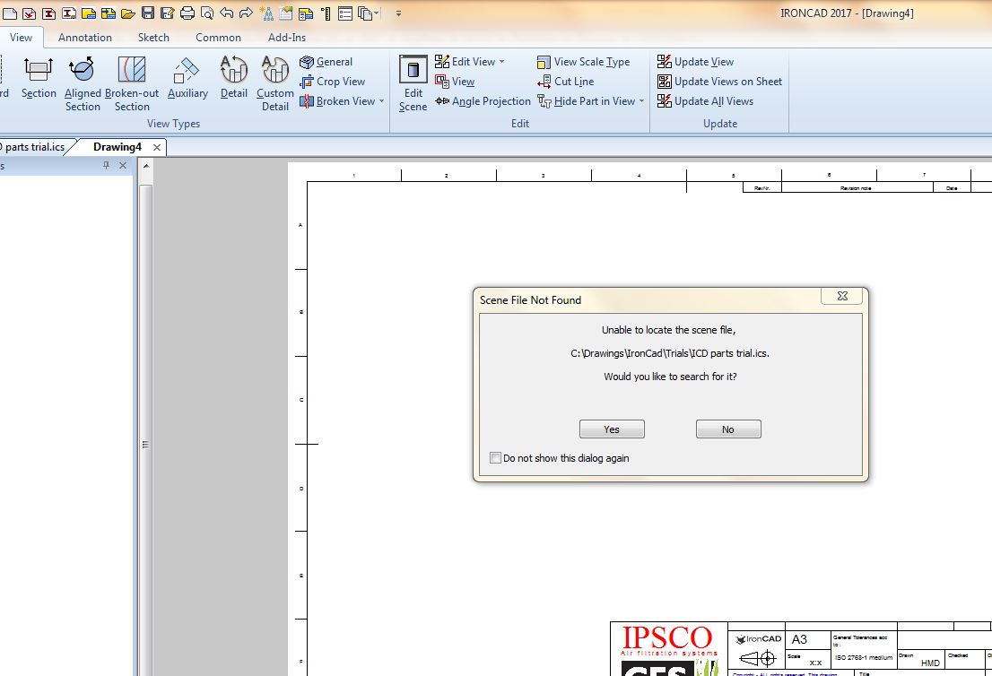
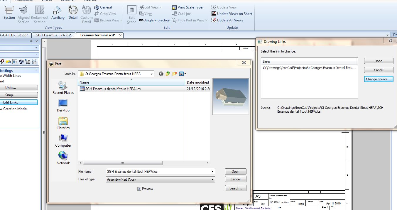
Further to the problem, I restarted my computer, worked on some other drawings and then tried to get the ICD 2D view working. This time I came up with the problem that the ICS file couldn't be found - see first attachment. So I started up a dummy drawing and got the same result - even though the ICS file clearly existed, ICD ( or windows? ) was looking in a previous directory ( see second attachment ). Even when I located the ICS with browse, I couldn't get the 2D views to show up - but they showed up in CAXA. Weird!
-
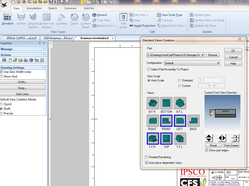
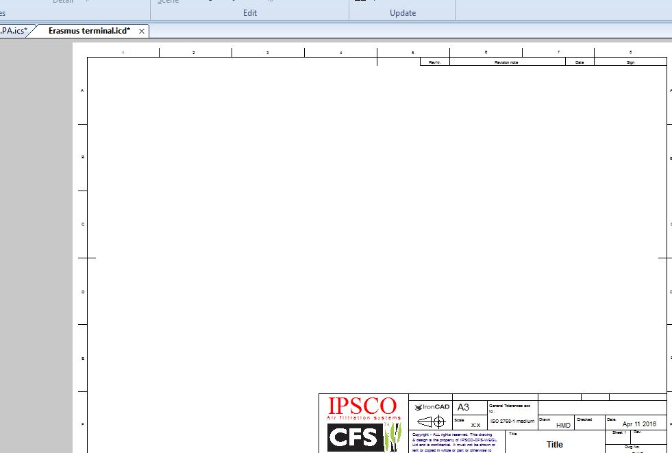
All of a sudden I cannot get any of the 2D views to appear on my ICD templates ( which have worked perfectly up until now ) The only changes I have made since they worked were; 1) Downloaded the 2017 Service #1 patch, and 2) Removed IC 2016 I have double checked that the links to the ICS file is correct. I have also opened previous ICD drawing linked to the same file, using the same ICD template, and the 2D drawings appear like they did previously - no change. Even using standard ICD templates - the 2D views do not show up. I can get the 2D views in CAXA interestingly enough. Further, the problem of getting ICMech Unold Export to work with fold lines showing, which Jonas helped me fix, still works perfectly so that part of ICD seems to work fine - however that 'Unfold' template is in a completely different part of my computer. So can anyone suggest what may have happened - either the Service #1patch ( which I doubt ) or removing IC2016 ? More importantly, how do I fix the problem?

-
Thanks Kevin. That hotfix worked well - see attached.

-
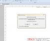
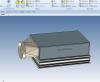
IronCad crashed during a blend operation. I was able to reproduce this several times. Below are the screen shots of the warning I got and the file I was working on at the time. I'm aware I should have backed out after the first warning, but even so it shouldn't crash like that should it?


-
Thanks Jonas. I'll look up that DesignDataManager. Cheers, Harley
-
Is there a way to look at an .ics file ( which could be a linked child file ) and ascertain if its actually linked and if so to what parent. I know you can look at 'file --> References' on any parent file to see what is linked, but doing it the other way around would be handy too. Yes... I did look back on history to see if this question had been raised before.
-
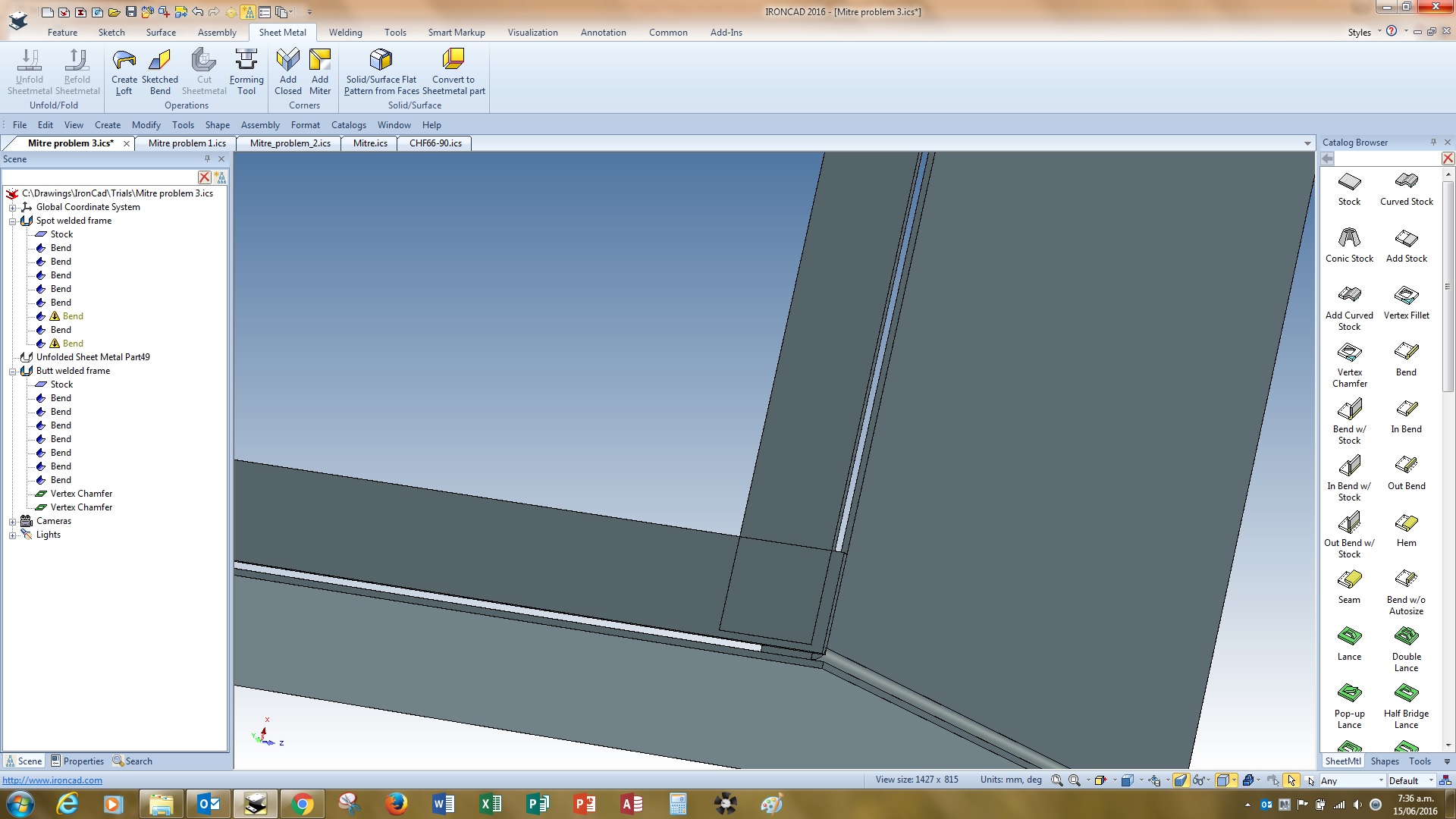
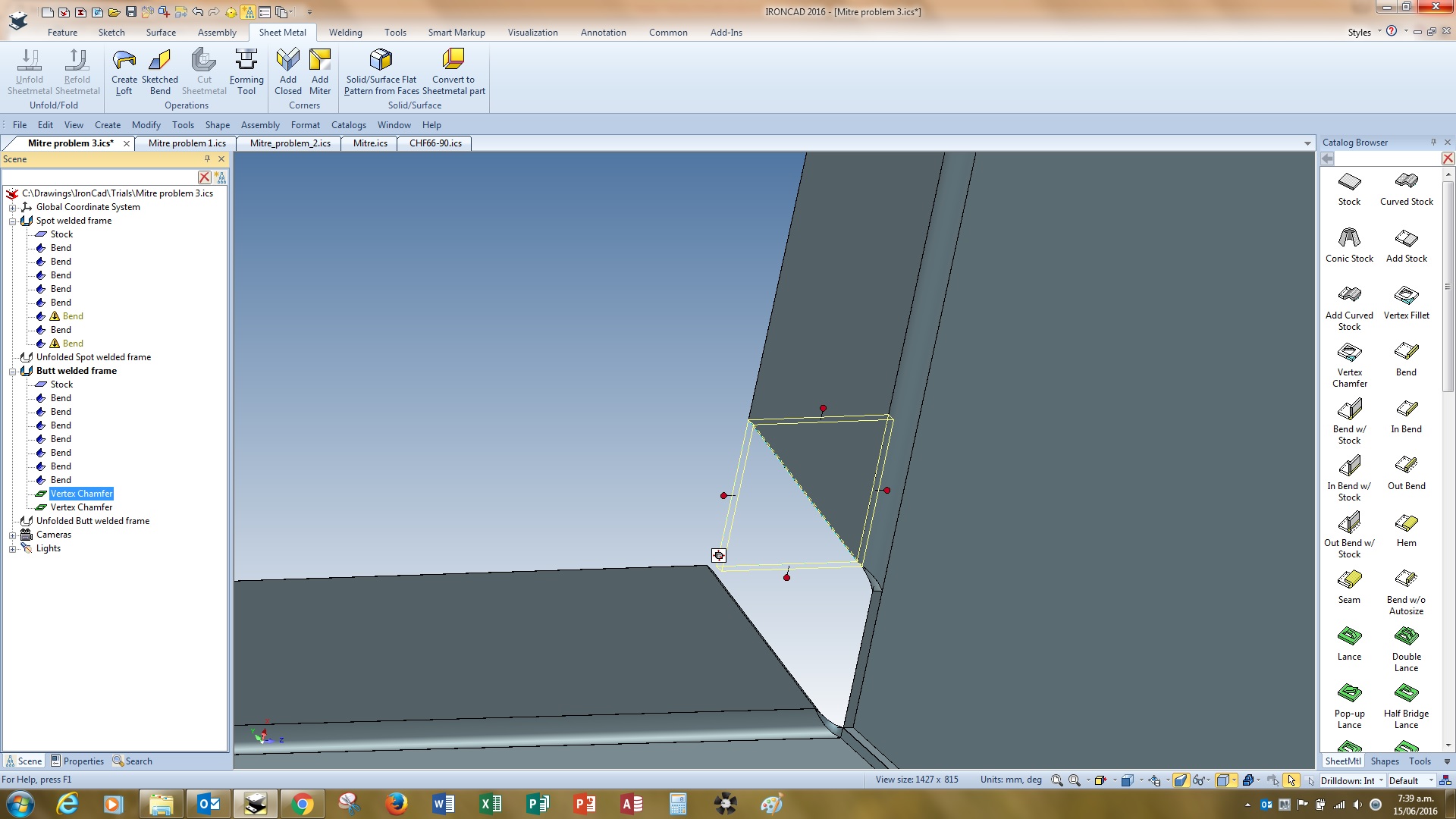
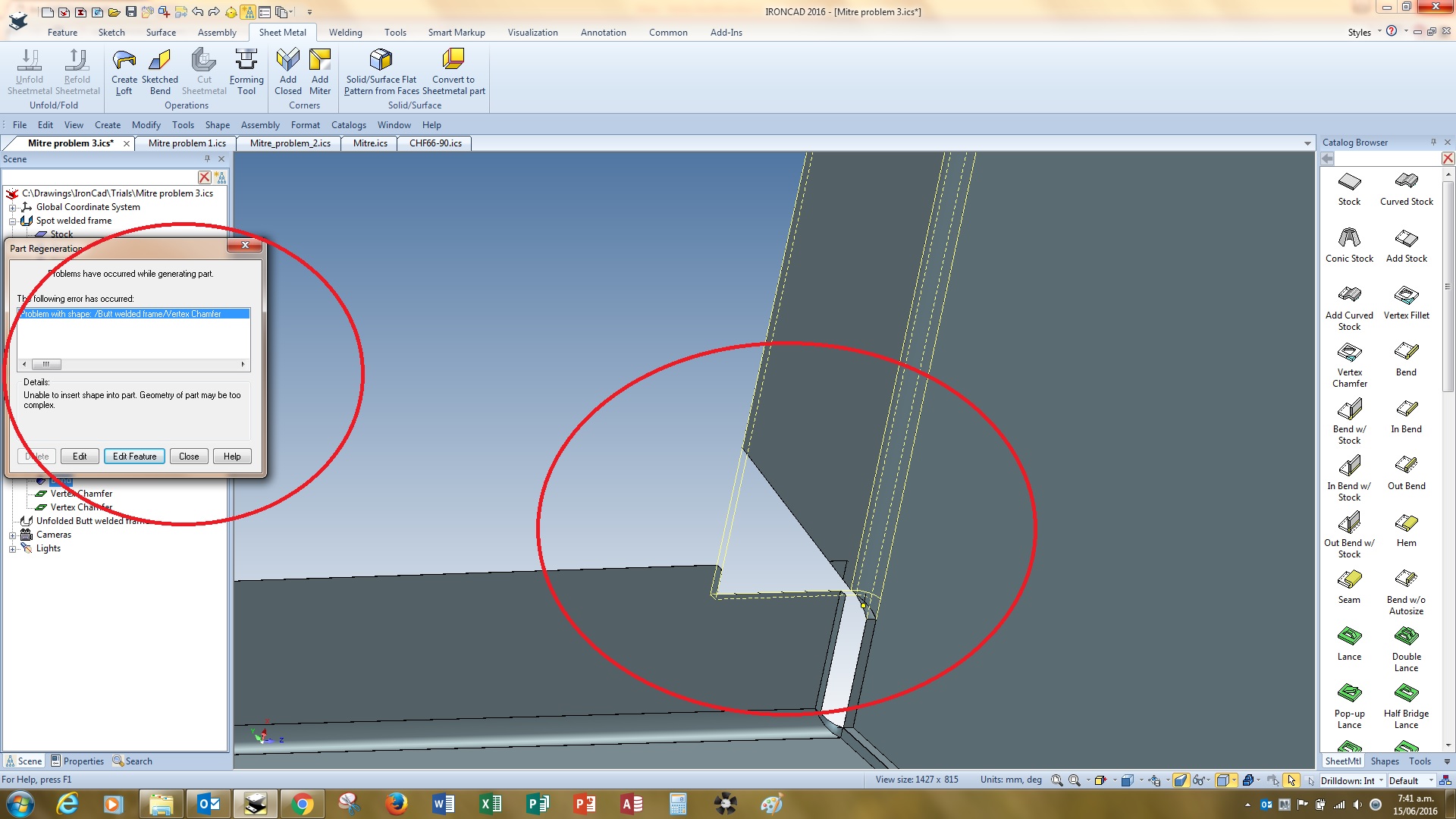
Thanks guys. Both methods from Cary and rsaucier are helpful, especially the create the miter with the option set to "Create Miter Flanges only" Cary's option of having the stock meet in the middle or anywhere away from the bend looks good but unfortunately isn't an option when making the product. However I still can't do what I need to carry out without creating problems. I tried using Cary's and rsaucier's method in the attached 'Mitre problem 3.ics Refer 'Mitre problem 7.jpg' - the result on the spot welded configuration was clearly not usable. 'Mitre problem 8.jpg is the butt welded option with rsaucier's gap applied and this allowed me to put the right relief of the bends and create a vertex chamfer. I had to pull one bend back to achieve this. However when I move the last bend towards each other ( 9.jpg and 10.jpg ) you can see that there is yet another problem created. Once the vertexes cross, it's WWIII. I have attached a frame system I drew a while back using bends and add stock. Refer CHF66-90.ics. This worked fine but was quite time consuming and if the outer sizes of the frame changed, what a mission it was to get it working right again. The other problem I have is that I can't remember how I actually did it - a function of becoming an old fart I guess Summary is that I was hoping the add mitre feature would reduce this type of work to a minimum amount of clicks and be relatively simple and for many applications this is the case. However for 'closed boxes with returns' it's still frustrating. Finally, can anyone explain why the unfold referred to in my first post looked completely different from the 3D folded model? ( 'mitre problem 3 and 4 .jpg' ) Mitre_problem_3.ics CHF66_90.ics