jolizon590016
-
Posts
1,662 -
Joined
Content Type
Profiles
Forums
Blogs
Downloads
Articles
Gallery
Everything posted by jolizon590016
-
H Slots and H Cylinders on unfolds not showing
jolizon590016 replied to HDEAR's topic in General Discussion
Thanks Mike for sharing. Brilliantly simple IC works with the beholder. Joseph -
A Guru is also in my wishlist. Out there a Guru in waiting. Joseph
-
Welcome Dries, I haven't gone this path myself but it something I do want to learn myself. I have been trying to decipher or venture Matt Lombard's SWX Surfacing and Complex Shape Modeling Bible on and off (perplexed) and hopefully translate things relevant with IC as my a project. I myself haven't fully understood the surfacing tools on IC and still peek at once in awhile. You might try to look at the post IRONCAD's cousin as there is more similarity with SE than SWX. You may find clues from Tushar as you are familiar with the SWX surfacing tools. Regards - joseph
-
H Slots and H Cylinders on unfolds not showing
jolizon590016 replied to HDEAR's topic in General Discussion
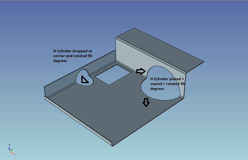
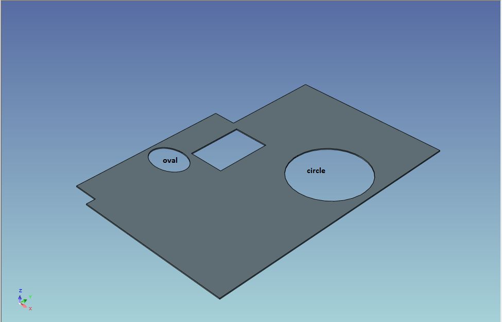
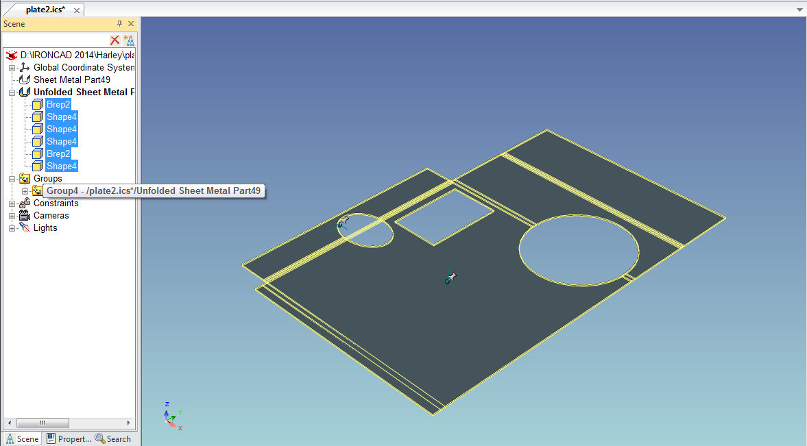
This may not be the answer to what you are looking for but others may have better knowledge on this placement of H parts produces different results unfolded result Selecting the components highlights in yellow, creating a group allows toggle group displays highlights regards plate2.ics
-
Box selection origin for 2D Profile Selection_difference.pdf
-
H Slots and H Cylinders on unfolds not showing
jolizon590016 replied to HDEAR's topic in General Discussion
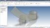
I was not thorough enough. I did the cylinder from the created loft from the sheet metal tab and using two identical 2D profiles compared to what I done earlier using catalog shapes. I hope this clears it up Joseph -
H Slots and H Cylinders on unfolds not showing
jolizon590016 replied to HDEAR's topic in General Discussion
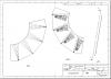
As the Ctrl + K slipped my memory, I did a CK version and applied the H Slot and H Cylinder. It appears on the unfold sheet metal. This corrects everything from earlier reply. However using shapes and extract pattern is something worth considering if you are in a rush though. Regards - joseph 1000sheetcylinder.ics -
H Slots and H Cylinders on unfolds not showing
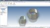
jolizon590016 replied to HDEAR's topic in General Discussion
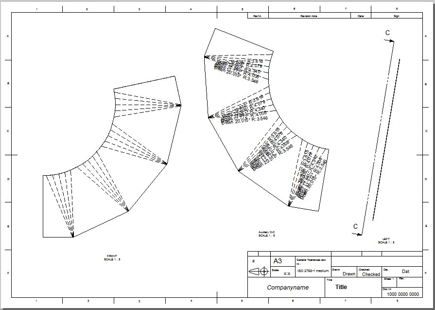
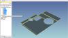
I used a cylinder from the shapes catalog and sized it to 1000 x 1000 x 1000 mm. I applied shell with a thickness of 0.8 and applied the H Slot and copied them with the TriBall. It does unfold or to be more precise as a flat pattern using the Solid/Surface Flat Pattern from Faces from the Sheetmetal tab and creates a new Part3 which cannot be refolded as it was not created as a sheet metal part that have distinct bend lines. I stand corrected on this again as the Ctrl + K will d let you do this. The slot (100 x 50) did transfer to pattern, So what I did was to measure it from the ICDrawing which gave a value of 100.085. But I understand your requirements to have the slots relative to the circumference, so what may be as work around will be to change the slot length and create a new flat pattern again. Tedious but will work. Someone might have a better idea on this Regards - joseph 1000cylinder.ics 1000cylinder.icd -
I created a weld guide, Weld.icc catalog and the part to work with. Joseph Part1.ics Inserting_Weld_on_Edge_Joints.pdf
-
Hi All, Here is Tushar Suradkar's Surf and Code site that is the closest IC cousin. I should have paid him visit earlier and more often now. http://surfandcode.blogspot.in/ SWX is the distant cousin by its choice . Great weekend - joseph
-
Thanks guys. That is why I am quite struggling is I can't to get it to work as in previous versions as I want to since I am so used to earlier versions that changes orientation on the scene from the camera setting when it had no camera picker options(Trispectives to ICv1.4). I must really getting rusty on this. I remember when I edit scene from the drawing I think Esc switches or x out you back to the drawing. Do you have any ideas about the bad cell instead of profile on edit. Thanks for your feed back
-
Hi, I am posting the finished article. Thanks - joseph Loft_to_sheetmetal_quick_guide_article.pdf
-
I will post the finished guide to Tips and Tricks section and at GrabCad. Thank to all who helped with this thread.
-
Mike, My apologies that I placed my thoughts right away. The process that I did is good for the scene and for catalog content items. I sensed there is more too it on what you have written. Instead of struggling to use Look At (F7) or as the process I am accustomed to, logic escapes me that using the Auxiliary View will solve this and it did. I just have to make sure that cursor highlights a green short parallel indicator rather than a point so it will be line on rather say spot on. Thanks for your assistance this an to the rest of the community. The only thing left I can not figure out will be the bad cell thing. Regards - joseph SQ2CIRC_8462.PDF Sq2Circ_8462.ics
-
Hi Mike, Tried to do as told. I got the position By Angle 80.532 so I subtracted it to 90 and got a difference of 9.462. What I was accustomed to doing is on the brep created by the unfolded part on the IntelliShape level, I rotate associated anchor point use the Triball, switch off the TriBall. And next what I do is select the brep again and tick of the anchor till it turns yellow and activate the TriBall to rotate if counter clockwise rotation of 9.462 so the anchor indicator will point at the right angle. So now it really face flat from the front view. I do it the other way if I want to maintain it original position when it was created and do the same on the part level so when I create a catalog part of an assembly I don't have to deal with the angle to reposition when it was drop back to the scene. As for this files it still shows the bend lines only even when it is really flat now at the front view. What I did found out is if the transition has 2 parallel adjacent sides, works perfectly. As you said it is flat when it unfolds from the adjacent face. Just a side note I really like using IC than anything else. In the past I have to work with SolidEdge which had a steep learning curve, but found IC .x_t neutral parasolid file exchange working perfectly with it with out reorienting position and missing data that needs to generated unlike with SWX http://www.ironcad.com/support/community/s...icons/icon8.gif sorry about that. I use the SE drafting component as required by the office for part of its documentation standard an found it can generate easily the files from IC and easily pick up data from it to use with the 2D annotation than ICD which I wish it could do. I was doing playground equipment that time and have to use a lot pipes for hand rails and creating centerline was easier. Still searching for the right process. Regards - joseph Sq2Circ_8462.ics Sq2Circ_8462.icd
-
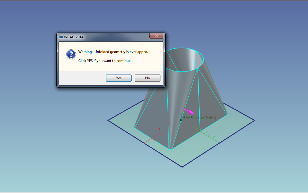
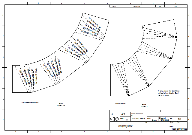
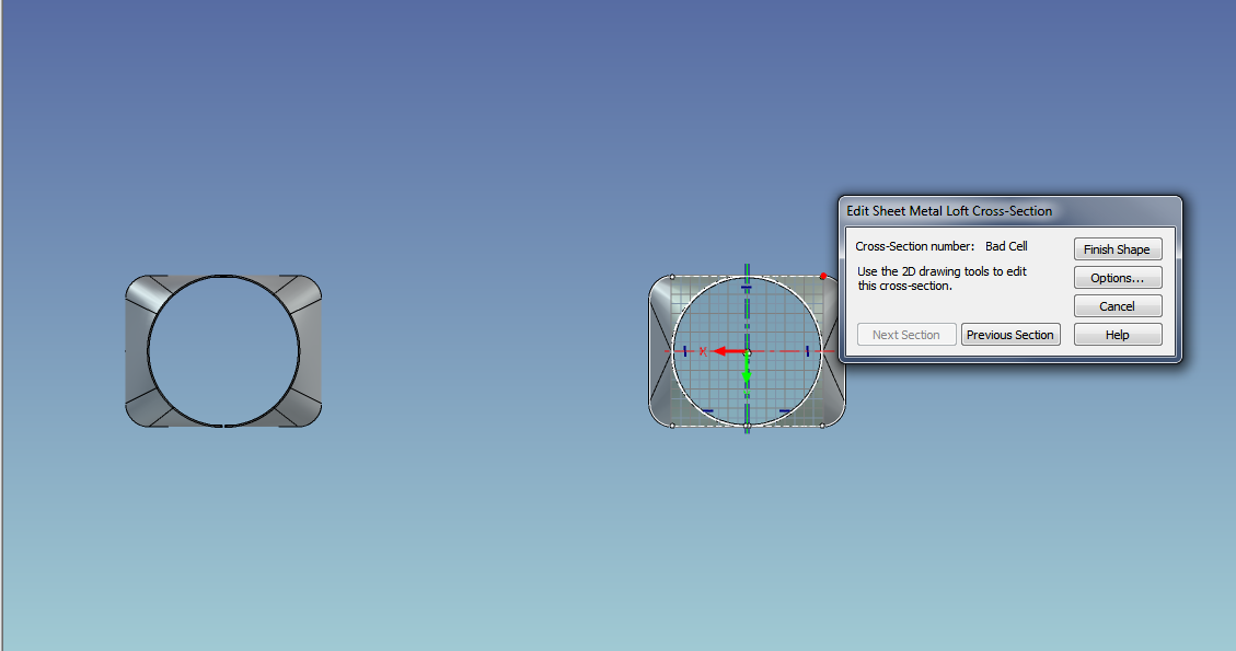
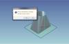
Hi, I am getting this: From the attached ics file. It does preview and create the bend lines but doesn't produce the manufacturing data on the icd sheet. Also attached is draft pdf Loft_to_sheetmetal_quick_guider1.pdf I also generated a side by side file comparison on icd between the 2 files I also tried to edit the cross section 2 of sheet metal loft1 from LoftSheetMetalck.ics file just to see if the over lapped message has to something to do with it. But why does Cross-Section number: Bad Cell instead of the Profile# Is this an indicator of a bad geometry creation or something that requires a mid section to loft with. Thanks, Joseph Rect2Circ.ics

-
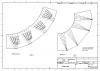
Was able to finally display the Bend line display at ICD LOFTSHEETMETALCK.PDF
-
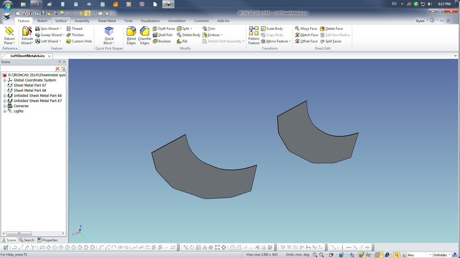
Hi Dariusz, That work and I hope it works for Harley too Should we set something for Default Kernel or run Ctrl+K on sheet metal projects? Likewise I can't generate the bend lines Again Thank you Joseph LoftSheetMetalck.ics

-
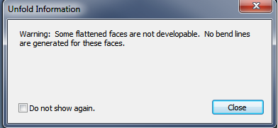
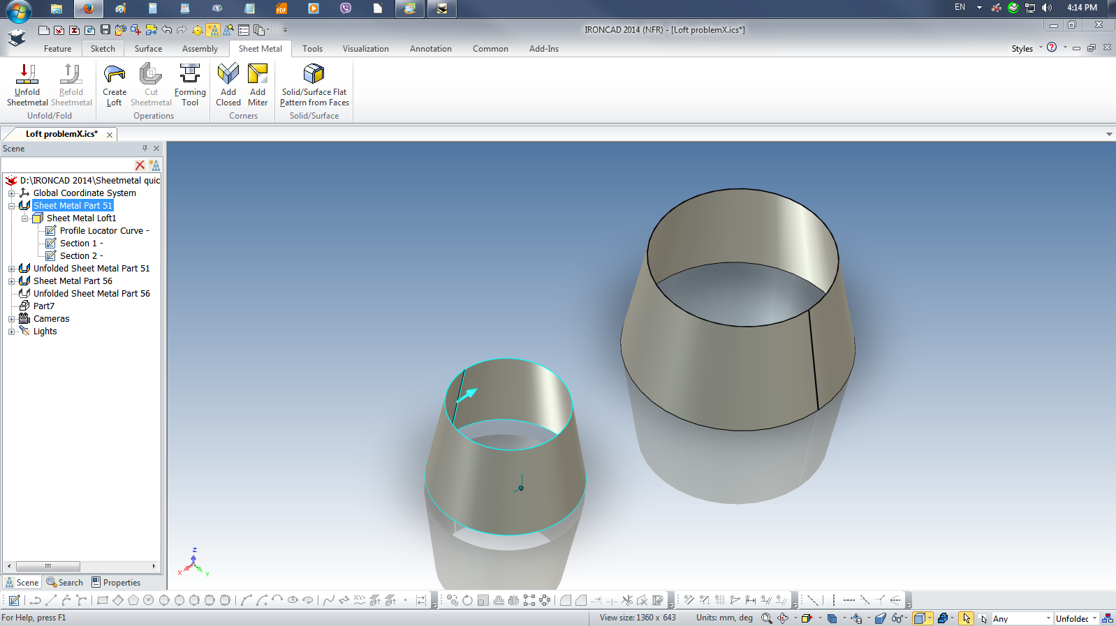
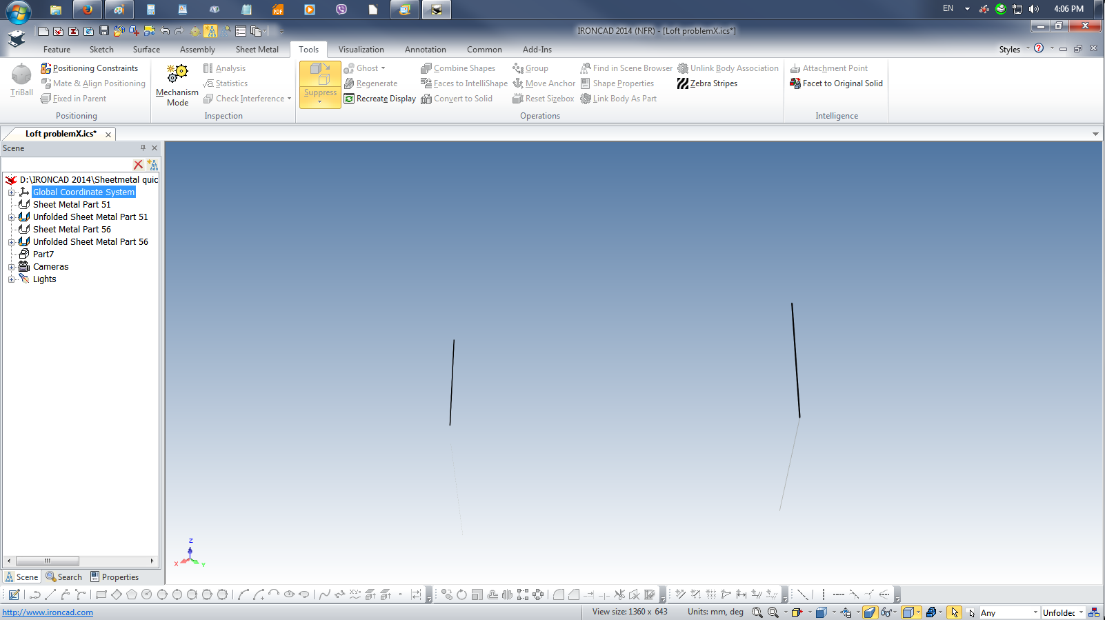
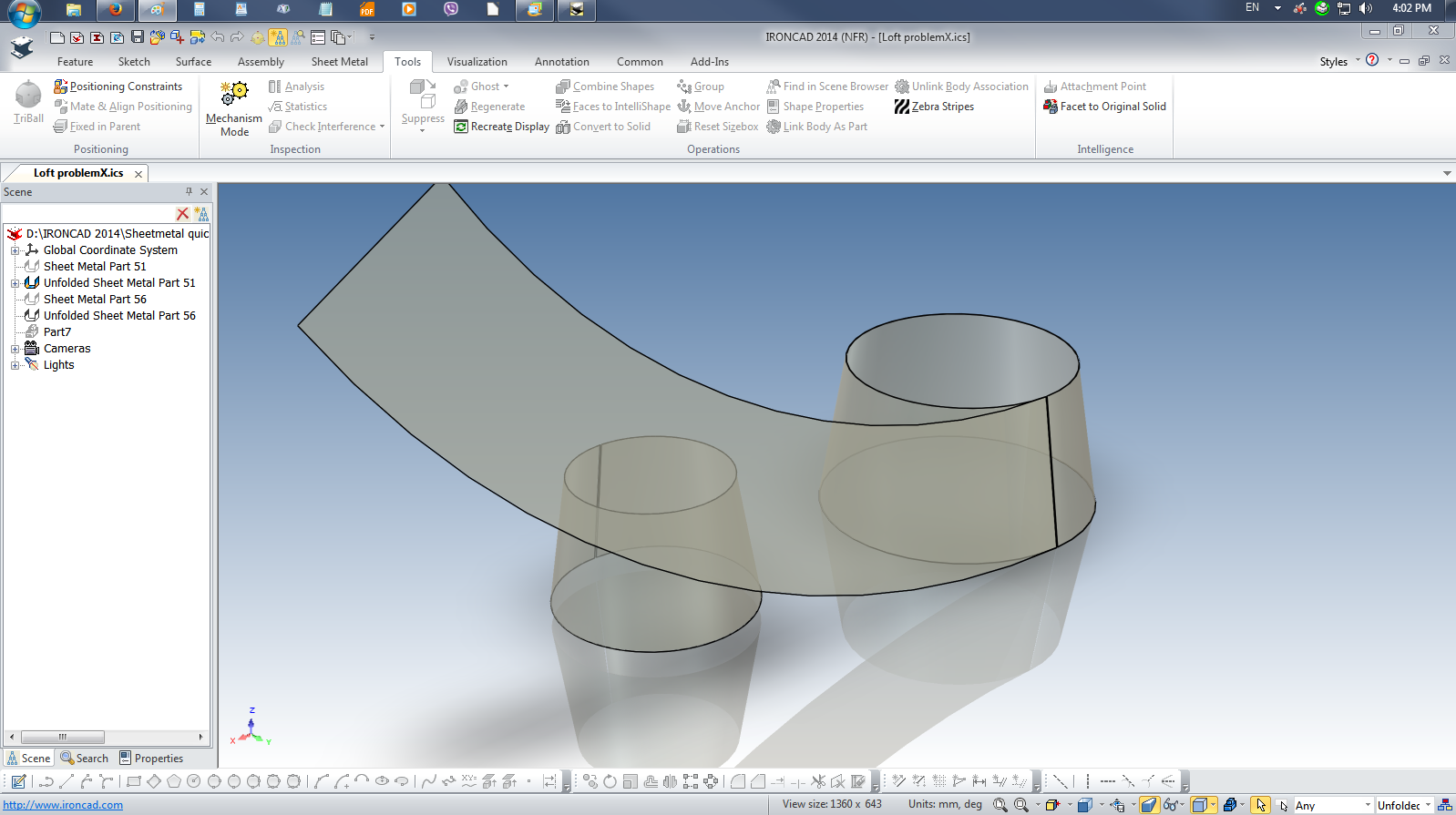
I have to file this to bug reports and hopefully a resolution can be made. I am experiencing what Harley has been doing and I am coming up with same results also with Dariusz video. I have tried it with my other notebook running 2014 also with the same outcome. I've use a 2012 no problems like Harley or mine do happen. With 2013, I get the This has been frustrating for Harley On the Loft ProblemX.ics file, Part51 was from Harley and Part56 is what I did. The only way the I was able to unfold it was using the Solid/Surface Flat Pattern from Faces tool the created Part7 Joseph Loft_problemX.ics

-
I have finished the IC Routing 101 and post the file at GrabCad IC_Routing_101fnl.pdf
-
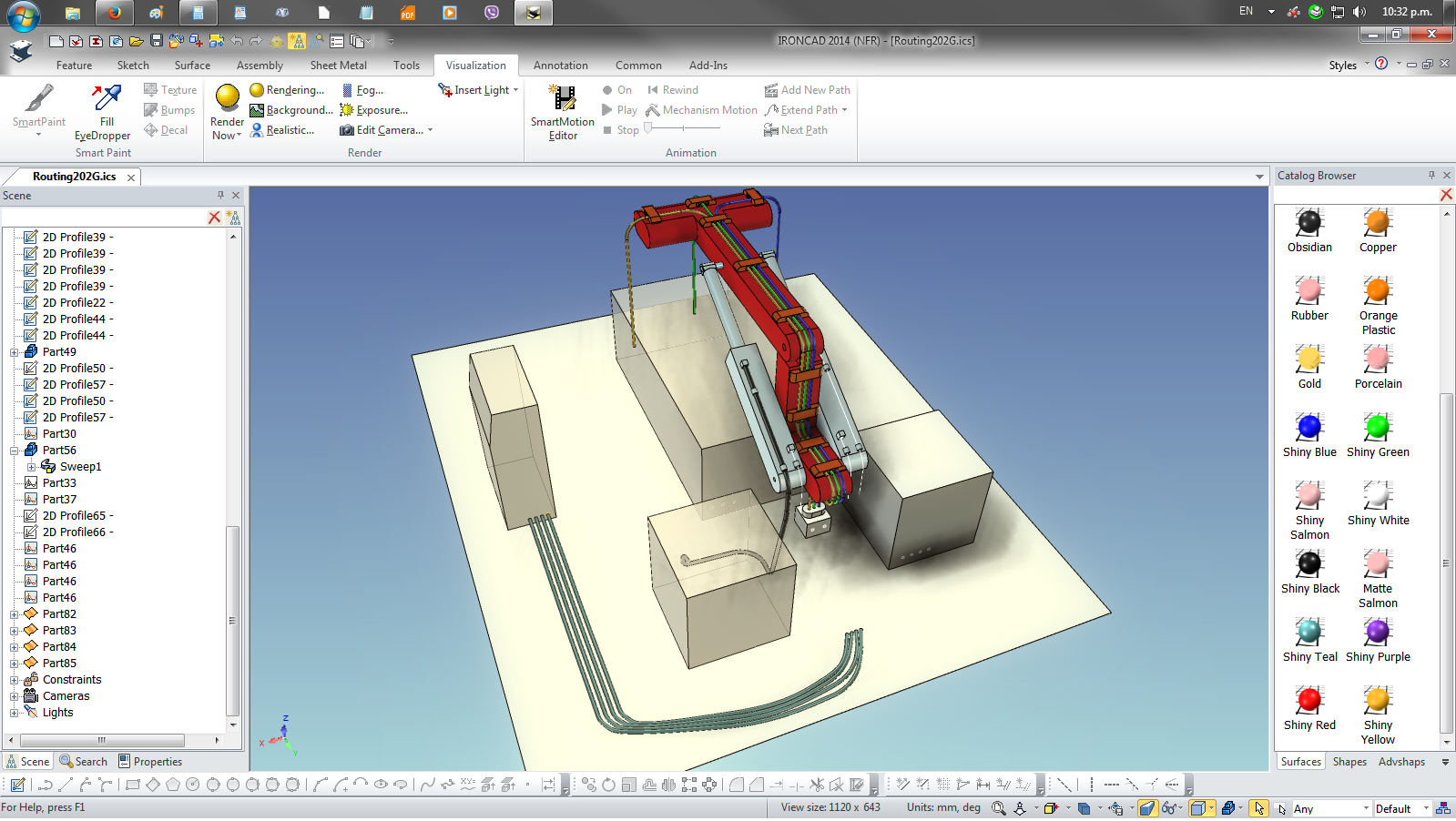
Routing hoses or electrical cables in machinery
jolizon590016 replied to jolizon590016's topic in General Discussion
The final guide posted on tips and tricks Thanks to all -
Routing hoses or electrical cables in machinery
jolizon590016 replied to jolizon590016's topic in General Discussion
Thanks Dallas. Getting rusty sight and mind. Copied 3D Curve path and edited each. Joseph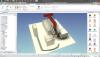
-
Routing hoses or electrical cables in machinery
jolizon590016 replied to jolizon590016's topic in General Discussion
This is the update version. I hope this presents the concept and allow viewer to do their work around on their end. Please suggest areas of improvement. -
Routing hoses or electrical cables in machinery
jolizon590016 replied to jolizon590016's topic in General Discussion
Thanks Tom. By the way while on the Shift Key subject, if you are facing a hole almost close to dead center to your view and drag a catalog shape to the center it doesn't fall to the center as the center point goes off as your cursor go past the diameter. Tried it with almost the keys unless a combination does the trick with out changing the view. This came up on a support call. Thanks again -
Routing hoses or electrical cables in machinery
jolizon590016 replied to jolizon590016's topic in General Discussion
Low resolution r2 Draft. Work in progress and will add wiring via connector. vertigo