jolizon590016
-
Posts
1,662 -
Joined
Content Type
Profiles
Forums
Blogs
Downloads
Articles
Gallery
Everything posted by jolizon590016
-
Best way to draw perforated or expanded metal?
jolizon590016 replied to HDEAR's topic in General Discussion
You got the right program tools to work with. I suggest convert it to .png so it is lighter. I usually start to apply it naturally and adjust the scaling factor if the holes project to big or small. Tom's work around is light on the resources. The Snipping tool is external and from Accessories, I hardly used it and this will only my second time to do so this way - thanks Tom. regards to all - joseph -
Best way to draw perforated or expanded metal?
jolizon590016 replied to HDEAR's topic in General Discussion
TILE_197.TIFTILE_205.TIFTILE_194.TIFTILE_195.TIF Additional images, hope this helps Once your done with a section that requires the holes, you may opt to copy the intellishape and suppress it for a future edit . While the other on display, combine the holes on the sheet so won't need to regenerate. However it makes it to a brep part. Others may have a better work around on this. -
Magnacad is moving beyond 3d space to the fourth dimension with the stylize 4 intersection/crossover of the infinity symbol wire frame. My old illustrator won't load now after a win7 install so don't have control on the drawing. magnimus or magnimux italics and slanted outline may be more progressive. still a draft concept

-
mag·nan·i·mous > magnanimus > magnimus with stylize + and infinity symbol or a dna helix third try
-
I had to download a trial of Revit so I can convert the file to .sat. Works great on my client's end. I do wish providers of the Revit .rfa files be more considerate in passing their file and collaborative to get the job done. regards - joseph
-
I have an inquiry on how to open Revit native files. What I know Revit should export or save as .sat, 3D dxf, Inventor or 3ds for IRONCAD to read it. Any advise or feedback is appreciated. Joseph
-
magna + innovation magnanova or novamagna with a stylize plus sign (+) and infinity symbol? Carlo can work on this!
-
So much for the french flavor. Kids will love the holiday spirit. magnavance. I give up on this and to come up with a saving grace.
-
magna + avancer = magnavancer maybe not well thought.
-
Is NEI NASTRAN still available for IRONCAD
jolizon590016 replied to Malcolm Crowe's topic in General Discussion
Hi Malcolm, NEI Nastran was snapped by AutoDesk late June. Please work with Go-Simulate for the mean time. The IC Team is working with this. Hope this helps. joseph -
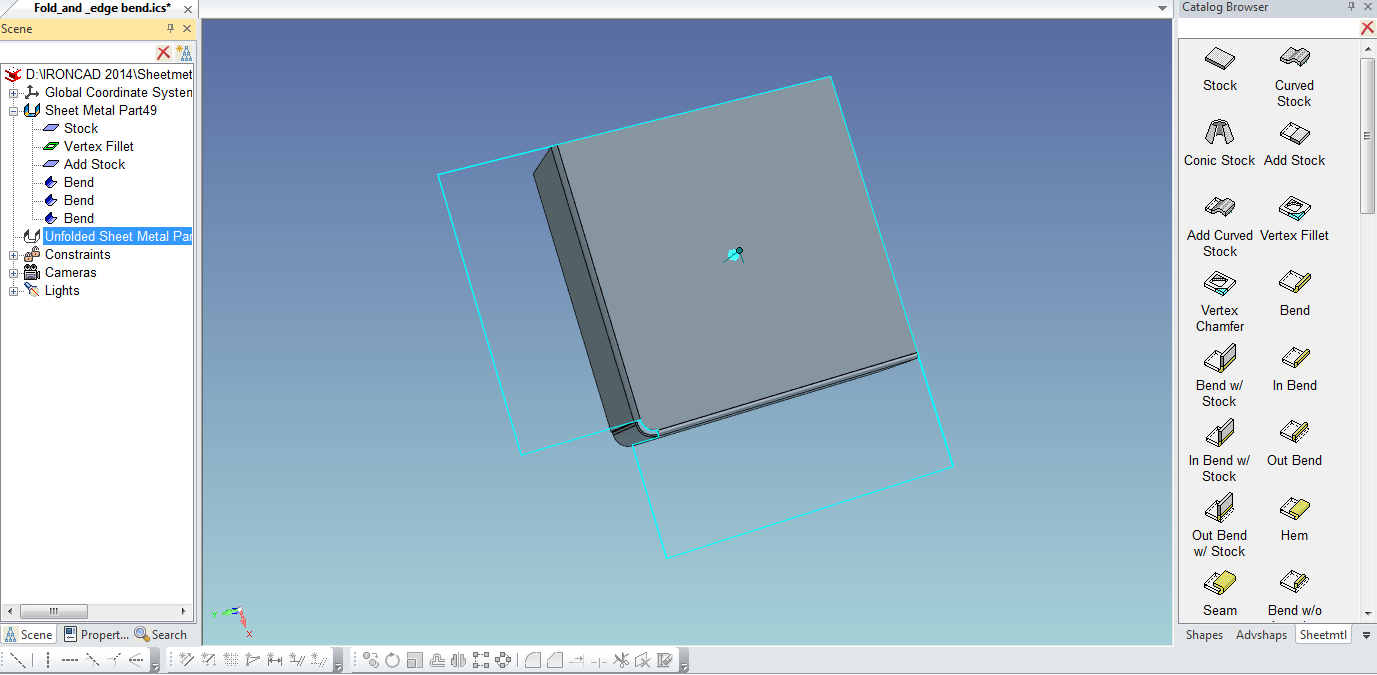
Nice to know you have sorted it out. Thanks for sharing your work around on this. The vertex fillet may work in place of the radius-ed edge. Hope this helps too. Fold_and__edge_bend.ics
-
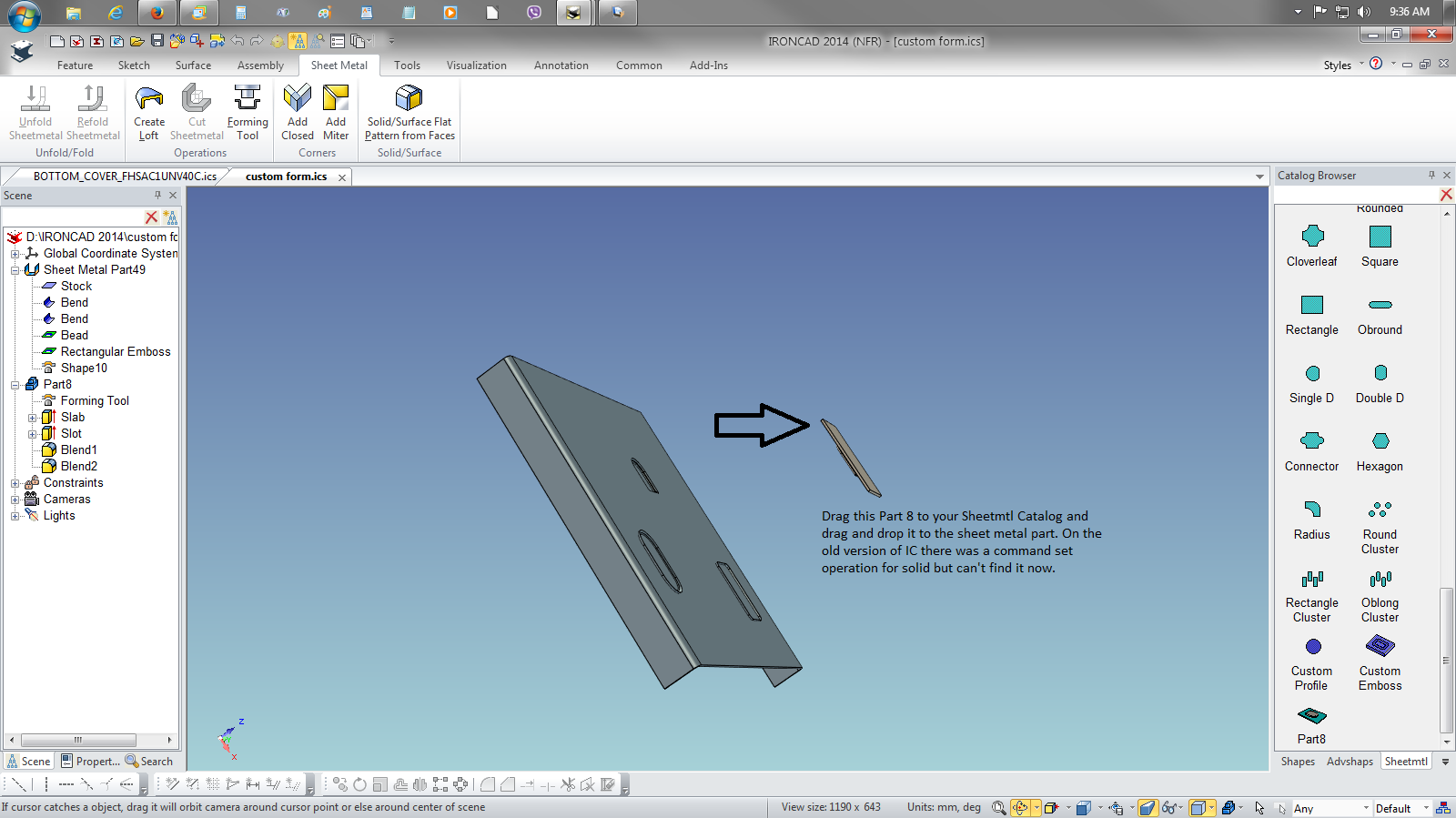
Here is the custom form I think you need. I hope I got it right this time. Rotate the model to view. regards Custom_Form_Shapes.pdf custom_form.ics
-
H Slots and H Cylinders on unfolds not showing
jolizon590016 replied to HDEAR's topic in General Discussion
A pdf guide was created from the work around process contributed by the members to this thread. It can be found on the Tips and Tricks part of the forum. The edit in the profile in the flat and to creep to bends will be the next guide to be documented. joseph -
A guide from the discussion on rolled sheet metal and techniques to create quickly. cheers joseph Quick_Sheet_Metal_Cyl_tips.pdf Proj1Cyl.ics Proj2BendCyl.ics
-
Wheel made from 2D file - how was this done?
jolizon590016 replied to HDEAR's topic in General Discussion
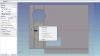
Great find. What he did was use a reference 2D drawing projected on a plane to trace. It was an ingenious way as some other 3D software (Intergraph or ICEM) have that kind of sketch feature. This feature previously not available midrange MCAD. You just have to discover a work around to overcome a feature that wasn't available as a standard. You have to create a 2D shape (box/square) as plane and project or apply the drawing as an image texture on the smart paint command after the 3rd LMB click as a surface/green overlay. The image sketch should have the right image scale so the 3D model will be close to the specified dimension. The TriBall showed its control over the design process. joseph Scene3.ics -
I think this from Mike at a different discussions will give the flow to work with but you have to create that dent profile/shape and set its operation not as hole but as a dent punch when you drop it to the sheetmtl catalog to function the way you like it. I can't exactly recall but to make it less complex but you have to tinker is to edit one of the sheetmtl catalog object's shape (dimple or the bead as you want it as a half slot like indents) that is almost close to what you want, save it with a new name and drop it back to the sheet mtl catalog as your custom dent. I wish I have saved that. joseph
-
I think the process require to get this done is with tool and die so it might be a stamped or formed piece of sheet metal similar to a sink where the cavity is drawn as Robert wrote. It requires more than folding process alone and IC and do the tool die. I found a guide: http://sheetmetal.me/ and http://www.sheetmetalguy.com/index.htm that can be of use for everyone. Hey Wes, welcome to the community - cheers Joseph thought of something give this a try

-
Thanks Cary for this guidance.
-
I haven't really delve with Draft. But your observation is correct as I tried looking back on the files I created and doing it on Draft. One thing I did notice though is that I don't need to do the auxiliary view as I did in lieu of F7 on the IC Draft. Someone will come with an answer. regards - joseph
-
H Slots and H Cylinders on unfolds not showing
jolizon590016 replied to HDEAR's topic in General Discussion
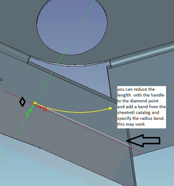
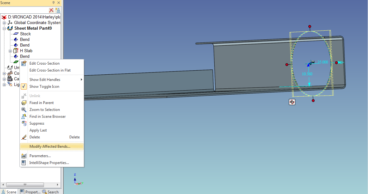
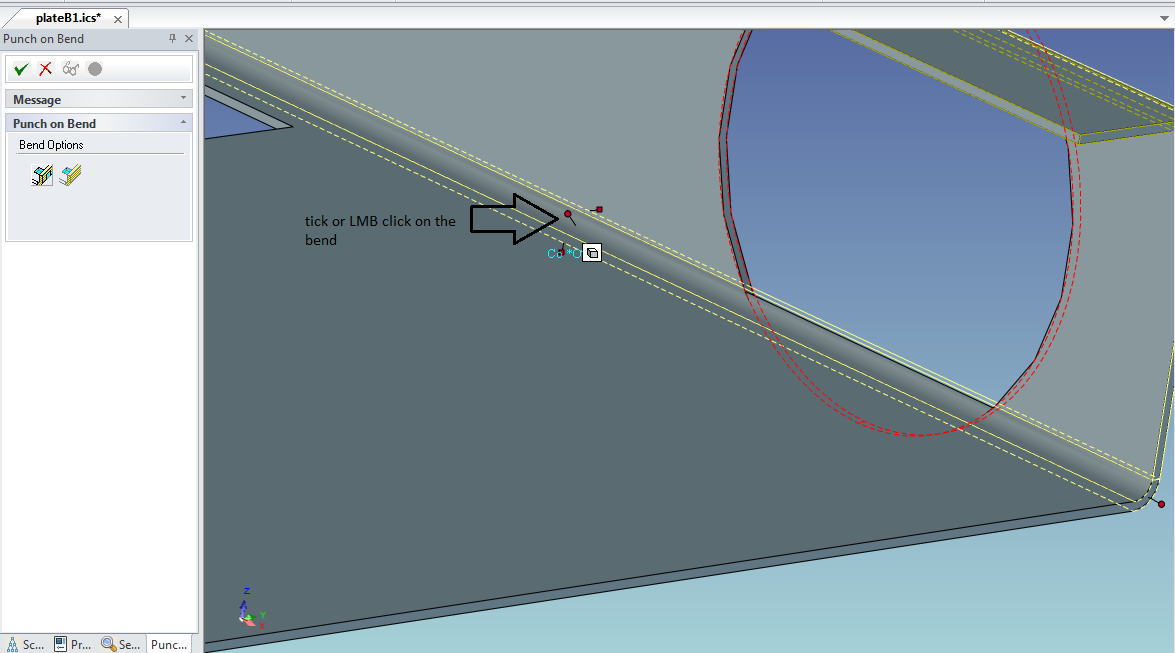
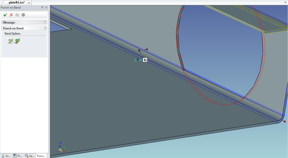
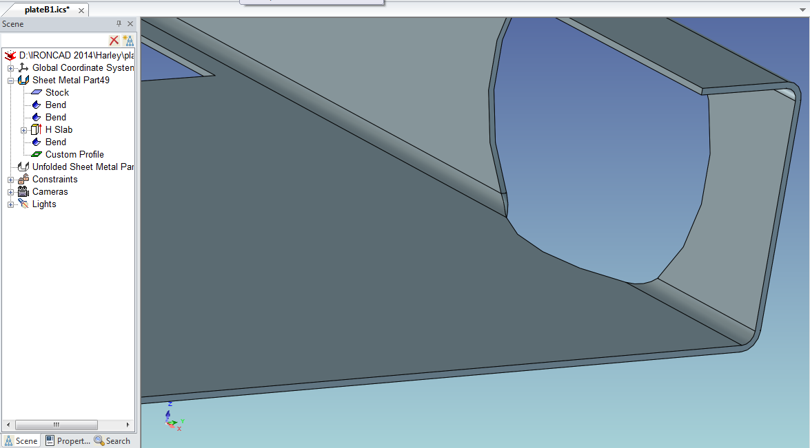
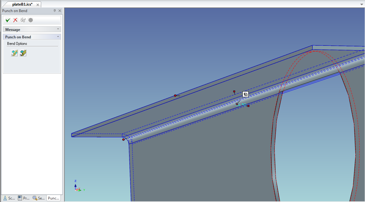
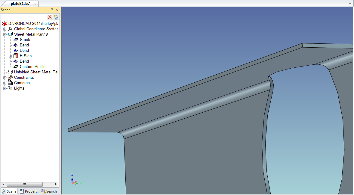
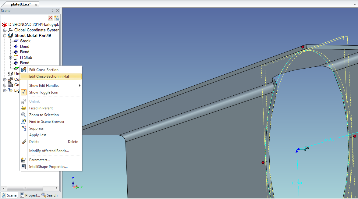
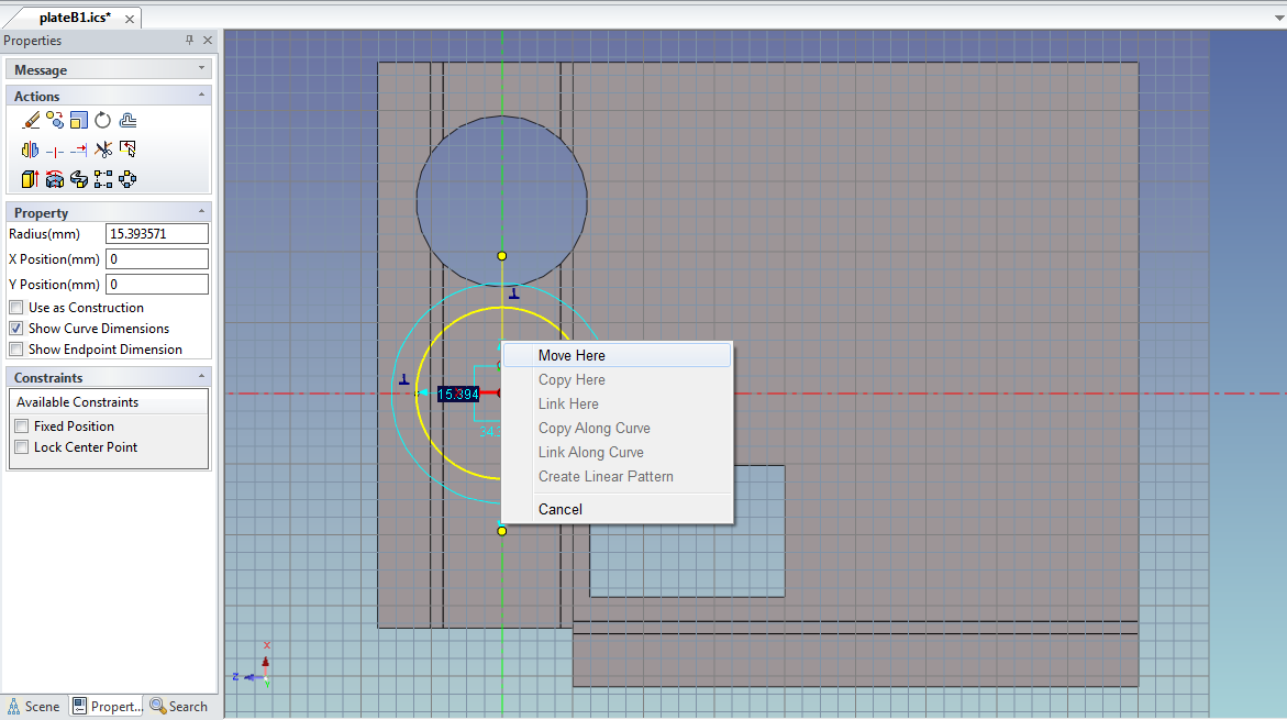
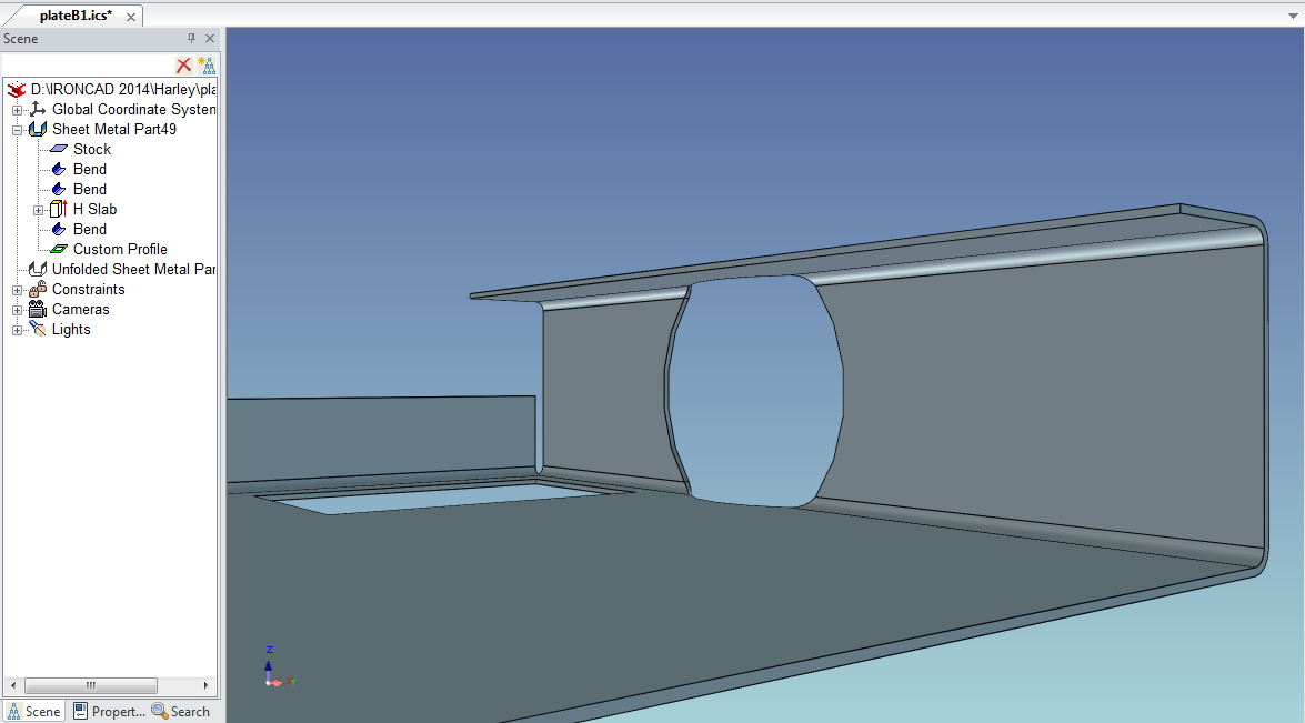
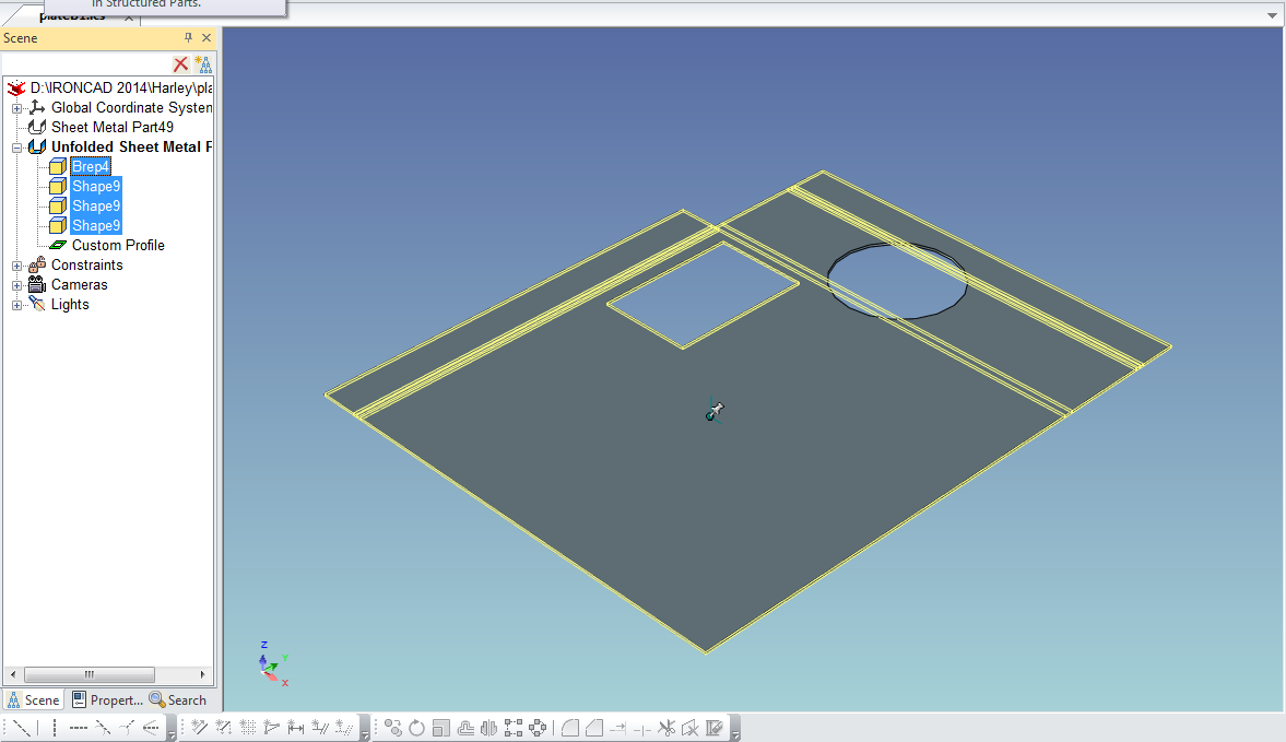
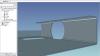
With Cary's, Jonas' and Mike's insight, I was able to do SWX penetration to creep to the bends correctly by Right-click Modify Affected Bends on the Custom Profile and move position in Right-click edit profile in the Flat. It may not be as single action as SWX but may produce what Dariusz did. Please follow the sequence off the images to view. Hope this add a much desired functionality on your end. joseph plateB1.ics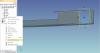


-
Hi, Recently been asked on how IC can work with its features on plastic injection mould design sans the mould tools from SWX. This may sound too broad, any contribution or insights will be sort of a good reference community wide. Regards - joseph
-
Spill the beans, it is getting there. Having it all built in will make easier and robust. Tom, any chance this is your calling. Joseph
-
H Slots and H Cylinders on unfolds not showing
jolizon590016 replied to HDEAR's topic in General Discussion
Thanks Jonas, this also taught me to make a hinge faster. This a better solution. Regards - joseph -
H Slots and H Cylinders on unfolds not showing
jolizon590016 replied to HDEAR's topic in General Discussion
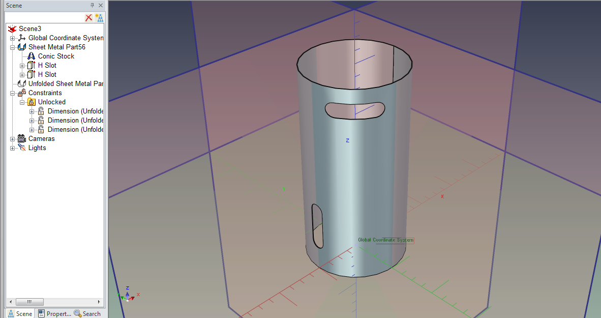
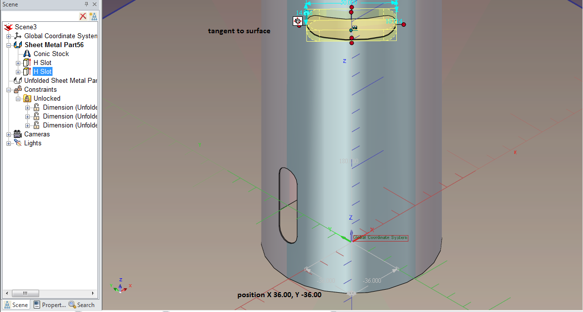
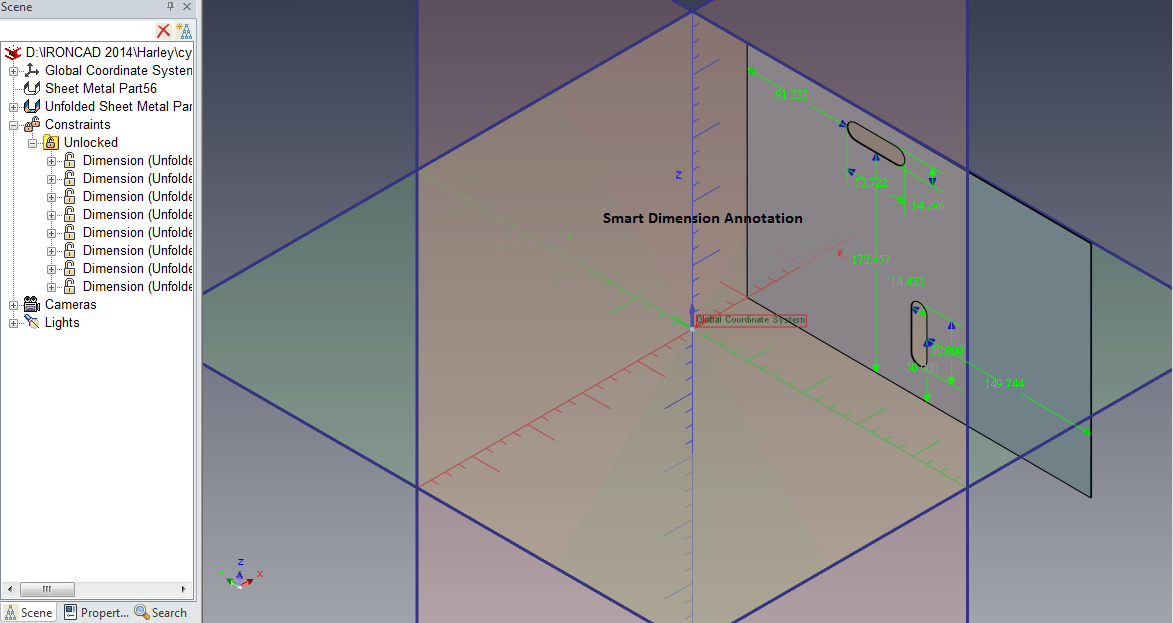
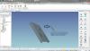
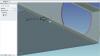
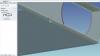
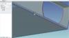
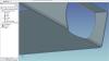
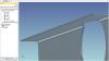
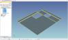
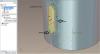
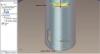
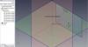
This is a refresh on me. IC does everything in 3D and all 3D editing is done in that space. However there is a pseudo 2D I think may work in this situation. I have placed the annotation text on the images on a sequence for guidance: If you change the values of the H-Slot postion and size, the Smart Dimensions updates on the unfold sheet metal part when you invoke the Sheet Metal Part Unfold. The correct preview will be updated after this. This is the nearest thing I have come up to currently. Precise positioning from the planes by switching plane views and with the TriBall features. I have attached the file and the close cylinder with a seam was done by Mike's way of using the Conic Stock. Regards - joseph cylinder12345.ics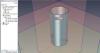

-
H Slots and H Cylinders on unfolds not showing
jolizon590016 replied to HDEAR's topic in General Discussion
As I gather it the rolled plastic are flow control regulator inserts acting like a scroll valve. Or each rolled patterned plastic sheet correspond a value. I hope I got that right.