Malcolm Crowe
-
Posts
1,760 -
Joined
-
Last visited
Content Type
Profiles
Forums
Blogs
Downloads
Articles
Gallery
Everything posted by Malcolm Crowe
-
Thanks for the various input. Until a fix can be implemented in the image export, the simplest work-around for me is to simply capture an image of the scene (since I don't have any unwanted lines in the scene view).
-
Within IC2014 SP1 I am unable to get the Configurations to store (or track) the Design Variations. I have tried "Adding" the design variations to the active configuration, but it doesn't work. I have experienced this problem in the past but thought is would have been fixed by now. Is anyone else able to get Configurations to store / track design variations?
-
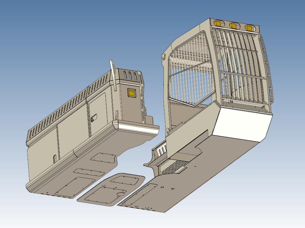
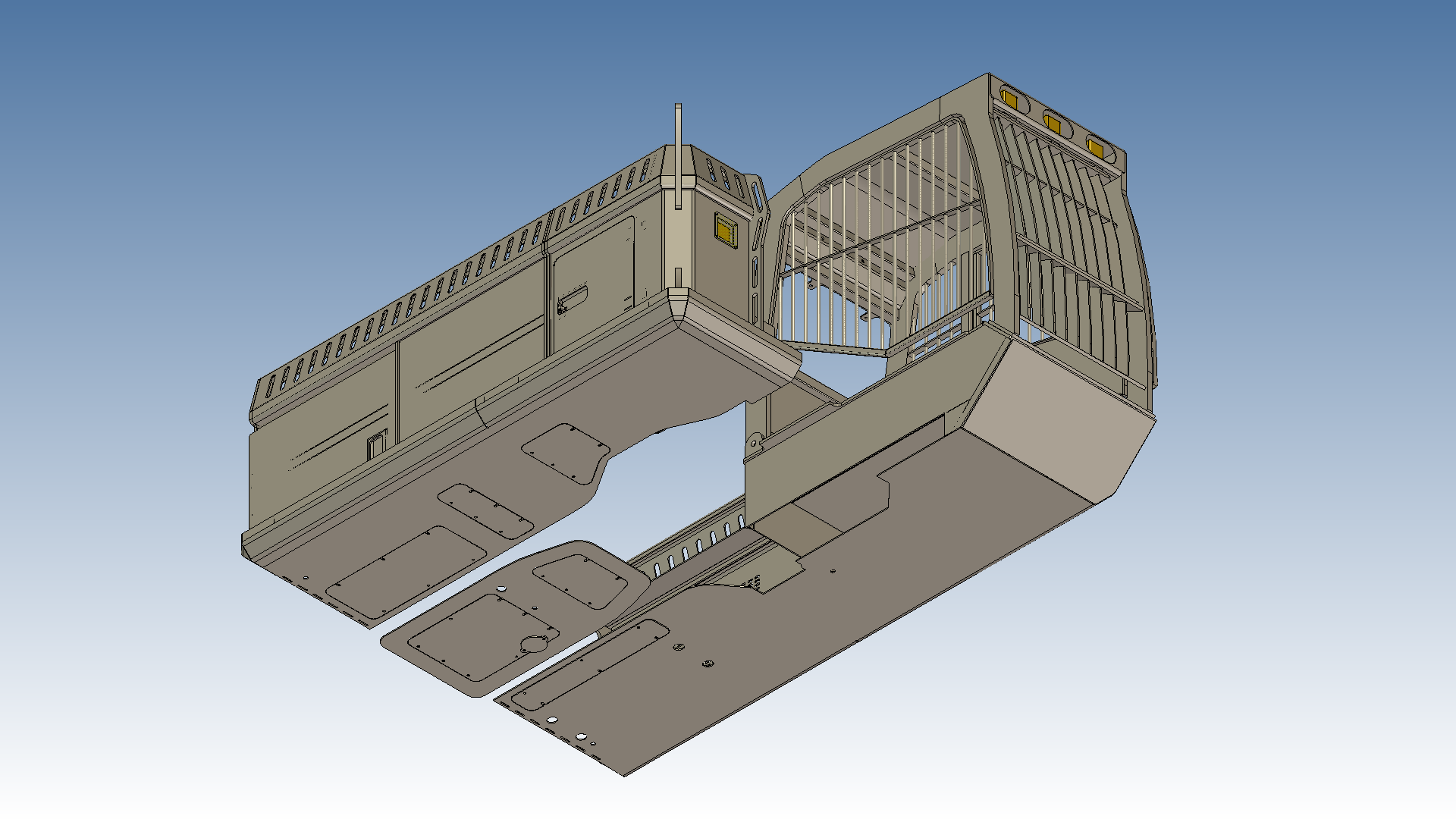
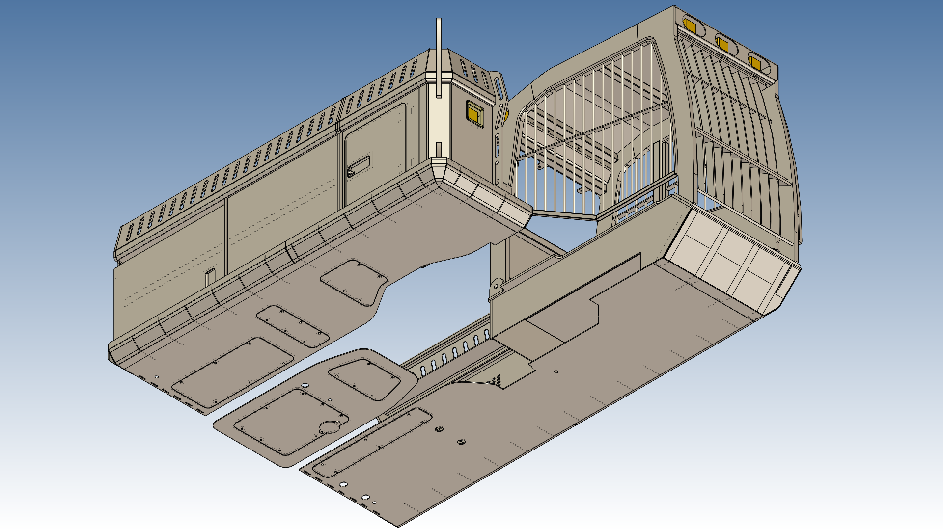
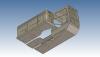
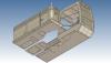
Thanks Cary and Joseph for the replies. "Perspective" was off in the view, but the same affect is seen with "Perspective" switch on. The lines just move (some disappear and others appear). Joseph, I also tried your suggestion of lowering the exported resolution but this made no difference to the lines also. The best that I have been able to do to improve the image is to switch to "OpenGL" in the scene Rendering settings and to set the "Manual Line Offset" to the maximum (200). Most of the lines disappear (see attached), but some still remain, so would appreciate a better solution if available.
-
Attached is an exported PNG image from IC2014 SP1 using "Screen Display Quality". When exporting images using "Screen Display Quality" I am unable to prevent extra lines from hidden parts from appearing. If I use "Advanced Realistic Quality" then this isn't a problem. However, I then loose the ability to have visible part edges, which is what I want in this instance. Is there a trick to exporting images, or is this a known problem / limitation?
-

Using Reference Surfaces with Structured Parts
Malcolm Crowe replied to Malcolm Crowe's topic in Tips and Tricks
Thanks Cary, for the tip about not having any parts "Active". So working within that limitation, it is first necessary to create 2D sketches without associations within the active structured part that you are creating. Then deactivate it if you want to create associations (constraints) with sketches in other structured parts, which will now be visible. This is really helpful to me as I prefer to (and sometimes need to) associate underlying sketches. -
Create Profile on X-Z and Y-Z Planes
Malcolm Crowe replied to Malcolm Crowe's topic in General Discussion
Hi Kevin, thanks for the reply. I get the same result as your video. I see now that my confusion was in the naming of the axes within the 2D sketch, verses the naming of the world coordinate axes in the 3D scene. The 2D sketch always names the axes as X-Y, and these aren't related to the world coordinate axes in the bottom left of the 3D scene. Happy now that I understand that. -
When working in structured part mode, while it is possible to reference 3D elements of other structured parts (such as faces and edges), it currently isn't possible to reference 2D sketches within those structured parts. If you are used to being able to do this in other CAD software such as SOLIDWORKS then this is the work around. Within the structured part that you want to reference, create a reference surface of the particular 2D sketch that you want other structured parts to reference. This surface will be separate body that can then be hidden or shown as required. In the attached sample assembly (IC2013PU1) there is an innovative reference sketch, and innovative part (1) that is referencing the innovative reference sketch. There is also a structured part (1) that is referencing the innovative reference sketch, while also containing a reference surface that structured part (2) is referencing. If you switch between the 2 design variations of the assembly then you can see that the relationships between the parts are maintained. In particular the position and outside diameter of structured part (2) which is driven by the hidden reference surface in structured part (1). Reference surfaces are also useful when exporting files in neutral formats to other CAD systems, as they can be used as reference planes and sketches which wouldn't otherwise be exported. Using_Reference_Surfaces_with_Structured_Parts_130727.ics
-
Within IC2013PU1 most of my work lately has been structured part mode where there is a lot of freedom in positioning and orientating the 2D sketch plane. I have just tried creating some 2D sketches in innovative part mode and have discovered that when I right click on either the X-Y and Y-Z planes and select "Create Profile", the resulting 2D sketch is positioned and orientated on the incorrect plane, whereas the X-Y plane works fine. Has anyone else been experiencing this problem?
-
Generating Line Elements from Exported IGES Curves
Malcolm Crowe replied to Malcolm Crowe's topic in Tips and Tricks
Hi Cary. This was my original approach. That is, extracting the 3D curves within the structured part so that the 3D curve would change with the model. However, NEI NASTRAN for IRONCAD wouldn't allow me to select these 3D curves (for meshing and setting of line element properties) when they were within the structured part. I could only get it to work when the 3D curve was a separate part. Malcolm -
This is a tip for generating complex "Line Element Models" as a single part for structural analysis purposes (such as within NEI NASTRAN for IRONCAD). Creating line element models of complex lattice structures using the "3D Curve" tool within IRONCAD isn't practical. A better way is to first construct these complex models as solids or surfaces (which can be parametric) and then extract the 3D curves from the faces using the "Extract Curve" tool. However, when the model becomes very complex with many faces, rather than selecting all of the faces for extracting the 3D curve, it is easier to export the solid or surface model as a "curve" IGES file, and then import back into IRONCAD (or other CAD or CAE software). Attached is an IRONCAD 2013 PU1 file demonstrating what is possible. In this I have constructed a part model of a lattice section using surfaces. This is parametrically driven with 3 design variations. I have then created a new part within this same file, where I have copied bodies from the first part. That is, I have copied 2 bodies (one after the other) using Design Variation 1, and then copied bodies using Design Variations 2 and 3. I have then used the Tri-Ball to position these bodies relative to each other. This second part (which now consists of 4 "Copied Bodies" from the first part) can then be exported as an IGES file. It is important that the output format is "curve" and that all surfaces are exported as NURBS. This is important if you want split faces to be exported as curves. Having exported this IGES file it can then be immediately imported back into IRONCAD as a single line element model (even though it was created from 4 bodies). This is shown in the 3rd created part within the attached IRONCAD model. This principle can be used with both surface and solid models, and can be applied to any type of application where line element models are needed. NOTE: Wherever edges of "separate" bodies meet there will be duplicate 3D curves overlapping each other in the resulting line element model. These duplicate lines can be deleted within the 3D Curve edit tool by selecting the overlapping line segments and pressing delete. In the attached example I have avoided this by avoiding duplicate edges in my surface model. I hope that this is helpful in demonstrating what is possible. Generating_Line_Elements_from_Exported_IGES_Curves_130724.zip