Malcolm Crowe
-
Posts
1,760 -
Joined
-
Last visited
Content Type
Profiles
Forums
Blogs
Downloads
Articles
Gallery
Everything posted by Malcolm Crowe
-
Hi Tom, I couldn't do much of what I do without "Structured" parts. In a similar way to IRONCAD's "Single Scene" environment, Structured Parts are a "Single Part Environment" where you can contain (and more importantly constrain) all of the sketches, 3D curves, surfaces and solids used in the construction of a part. In this particular application, Structured Parts allows us to constrain a "solid body" (our reference sphere), to a "point" in our structured part, that can move in 3 axes. To achieve the 3 axes, we need 2 sketch planes. The position of the 2nd sketch plane is driven by the point in the 1st sketch. The steps are as follows, and is demonstrated in the attached movie. 1. Create Structured Part (automatically become active) 2. Create XZ Sketch (Plane/Face) - Insert "Point" within the sketch - Add the 2 "Dimensional Constraints" to the "Point" 3. Create YZ Sketch (Parallel to Face at Point) - "Project Constraint" the "Point" from the 1st Sketch - Insert a new "Point" - Add a "Horizontal Constraint" between the new "Point" and the "Projected Point" - Add the 3rd "Dimension Constraint" 4. Drop a "Reference Sphere" into the scene (location not important) - Edit the "Sketch Position" for this sphere - "Parallel at Point" to the 2nd Sketch Plane and it's Point - Set the "Origin" at the same Point (of the 2nd Sketch) - Check that "Fix to Reference" is selected. 5. Set "Points" as "Construction" within the sketches, so they don't show (optional and not shown in movie) 6. Deactivate the part (not shown in movie) Hopefully you can see that the "Sketch Positions" are the key. That is, ensuring that they are referenced (and fixed) to the correct points. Malcolm IRONCAD_2017_PU1.1___Parameters_for_Scene_Position___Creation.mp4
-
Hi Tom, I use "Structured Parts" to achieve this in two different ways. 1. The part that you want to position is the "Structure Part", with the "Bodies" positioned relative to that part's origin. 2. You create a "Structured Reference Part" that is fixed in the scene, and to which the other parts are constrained. The attached movie and scene file demonstrate option 2. Malcolm Scene_Position.ics IRONCAD_2017_PU1.1___Parameters_for_Scene_Position.mp4
-
Thanks for the Graphical Performance Improvements in IRONCAD 2017 PU1. I have noticed an improvement in my laptop's ability to manipulate large assemblies, where it previously struggled. Malcolm
-

Rendering Driver - OpenGL Suddenly Slow
Malcolm Crowe replied to Malcolm Crowe's topic in General Discussion
Thanks Kevin. Updating my NVIDIA Quadro driver fixed the problem. The OpenGL and OpenGL2 rendering drivers work as they should again. Malcolm -
I normally us OpenGL2 as my Rendering Driver of choice. However, during the past few days the graphics performance of IRONCAD has dramatically slowed, with jerky movements during zooming, panning and rotating of 3D models and 2D sketches. I don't know whether there has been an update in Windows 10 that may have caused it, but both OpenGL and OpenGL2 have taken serious performance hits. When I switch the Rendering Driver to DirectX9 then all works well (fast and smooth). Is anyone else experiencing a performance change when using OpenGL Rendering Drivers? Malcolm
-
I have seen the same disappearing view behavior in CAXA after install patch 1. Starting in the suggested Administrator Mode seems to have fixed the problem so far (working back in user mode). Malcolm
-
Thanks Tom. I have previously checked this product and think it has some interesting features. Malcolm
-
Changing Color of 2D Profile Geometry Indicators
Malcolm Crowe replied to Malcolm Crowe's topic in General Discussion
Thanks Kevin. That worked. Interesting though that I was able to change some other colors without restarting. Malcolm -
In the attached movie I am unable to change the color of 2D Profile Geometry Indicators. Is this a bug in IRONCAD 2015 PU1.1 or am I doing something wrong? Malcolm IRONCAD_2015_PU1.1___Changing_Colour_of_2D_Profile_Geometry_Indicators.mp4
-
Hi Brent, There are 2 places that you need to look in CAXA when it comes to Item Number Bubbles. 1. Check that the "Shape" option is selected in the "Item Number Style" that you are using. 2. Then within the "Fill BOM" you need to select the type of "Shape" (Frame) that you want displayed. Unfortunately this part isn't obvious and is missed by many. Hopefully the attached movie helps. Malcolm CAXA_2015_PU1.1___Item_Number_Bubbles.mp4
-
This previous discussion may help. After adding your custom property in the 3D model update the BOM within CAXA to check the spelling of the "Property Name". You need this to use for "Matching" with your "Attribute" Name within CAXA's options. http://www.ironcad.com/support/community/i...ic=10422&hl=bom Malcolm
-
Getting rusty on circular placement of text
Malcolm Crowe replied to jolizon590016's topic in General Discussion
Not sure if this is what you want to achieve, but you could create the text within CAXA using the "Arc-Aligned Text" tool. Explode the text twice. The first time explodes the text to "letters". The second time explodes those letters down to line elements. Then import the CAXA drawing into a 2D sketch within IRONCAD. From this you can then extrude "add" or "remove". In the attached example I have demonstrated this. Malcolm IRONCAD_2015_PU1.1___Imported_Arc_Aligned_Tect.mp4 CAXA_2015_PU1.1___Arc_Aligned_Text.exb IRONCAD_2015_PU1.1___Arc_Aligned_Text.ics -
I agree that draft analysis is the critical missing tool with mold designers in mind. Parting line tools would be nice to have as well, but this function can be done manually with other tools (such as surfacing) within IC. Malcolm
-
Does TRANS Recognize and Import Cosmetic Threads
Malcolm Crowe replied to Malcolm Crowe's topic in General Discussion
Thanks Kevin. -
Normally I work with CAD neutral PARASOLID, ACIS or STEP files when receiving files from other CAD systems. This requires adding cosmetic threads to the 3D models after importing. Does TRANS for IRONCAD and IRONCAD DRAFT recognize and import cosmetic threads from other CAD systems? Malcolm
-
Imported Chamfer Face to Intellishape?
Malcolm Crowe replied to Malcolm Crowe's topic in General Discussion
Hi Kevin, It must have been longer than I thought since I last converted a chamfer on an imported part. I am working with a lot of imported parts at the moment which is the reason for just noticing that it isn't working now. I hope that the intention for IRONCAD is to be able to recognize and convert more faces to Intellishape, rather than fewer. Malcolm -
From memory I used to be able to convert imported chamfer faces to Intellishapes. But in IRONCAD 2015 PU1.1 I am unable to do that any more. Has something changed or am I missing something? Malcolm IRONCAD_2015_PU1.1___Chamfer_Face_to_Intellishape.mp4 Cosmetic_Thread_Part_from_PARASOLID.ics
-
2D Sketches Catalog - Axes Orientated to View
Malcolm Crowe replied to Malcolm Crowe's topic in Tips and Tricks
Hi Joseph. Attached is a movie showing a sketched created on the XZ plane using your scene. As you can see, when viewed using the front camera the orientation of the X and Y axes is incorrect. Malcolm IRONCAD_2015_PU1.1___Orientation_of_Front_Sketch.mp4 -
2D Sketches Catalog - Axes Orientated to View
Malcolm Crowe replied to Malcolm Crowe's topic in Tips and Tricks
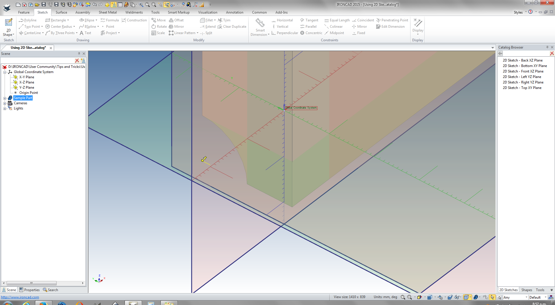
Hi Joseph. In my opinion (which isn't necessarily the right one), IRONCAD only gets the orientation of the sketches correct for the Top and Right views. All other views (including Front) are orientated with the sketch axes the wrong way. I don't understand what you were trying to explain, so I have attached a movie demonstrating the problem with sketches relative to the Bottom, Back and Left views. For sketches created this way I often need to first orientate the blank sketch to the desired orientation using the TriBall, so that the axes are consist with the view that I am using. The other attached movie demonstrates a 2D Sketch being dropped onto the YZ plane to create axes orientated to the Left view. The sketches can be dropped directly onto part faces as well; however, the orientation of the part's anchor is important as it influences how the dropped sketches are orientated (see attached image). When building up large assemblies I often need to create 2D Sketches that are orientated to different views, so that I can see relevant features or parts that aren't visible from other views. The sample part in the attached movies is a simple example, as it has a feature that isn't visible from the Top, Front or Right views. I'm happy to learn a simpler way to achieve the desired result if one exists. Malcolm 2D_Sketches_Catalog___Left_View.mp4 IRONCAD_2015_PU1.1___Orientation_of_Bottom___Back___Left_Sketches.mp4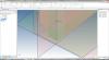
-
One of the confusing things when starting a new sketch on some of the standard planes, is that the XY axes of the sketch are orientated differently to the view (front, back, left, right, top, bottom). Attached is a Catalog of 2D Sketches prepared for dropping onto the different standard planes (or parallel part faces). Once dropped on the plane use the TriBall can be activated to position where you want. Alternatively you can set the sketches in the catalog to automatically activate the TriBall when dropped. Also attached is a movie demonstrating the dropping of these 2D sketches from the catalog. Malcolm 2D_Sketches.icc 2D_Sketches_Catalog.mp4
-
For the past 18 months I been using a DELL PRECISION M6700 with the QUADRO K3000M with 2GB GPU memory. Driver 347.52. 3D application controlled. As a comparison, I haven't noticed any performance issues compared to another workstation using a QUADRO K1200 with 4GB GPU memory. Malcolm
-
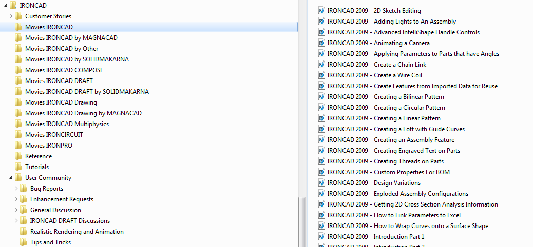
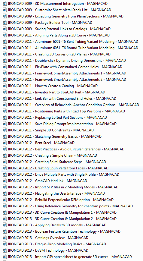
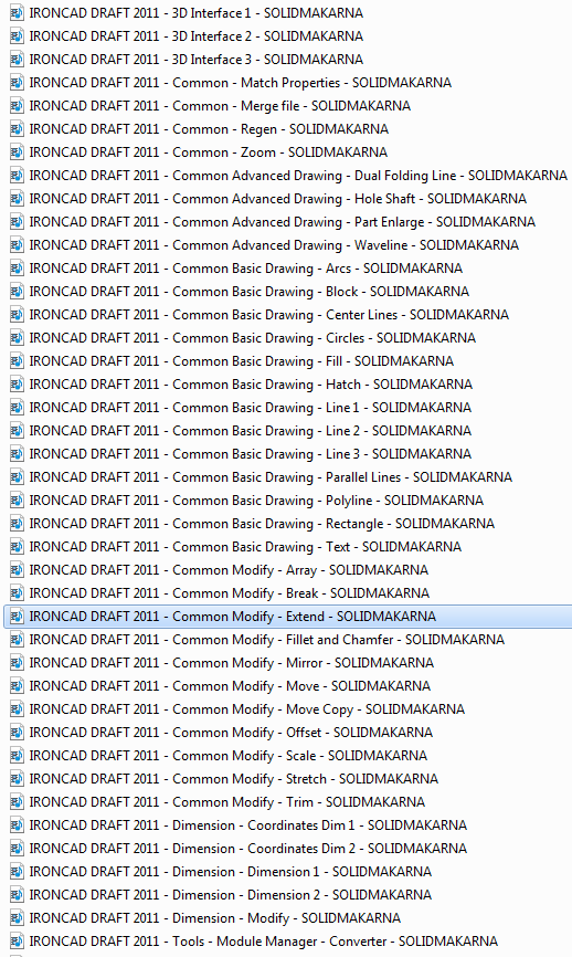
When it comes to YouTube videos I have found the following contributors to be good resources. IRONCADTeam MAGNACAD SOLIDMAKARNA (the audio is in Swedish but still helpful) The attached images are just a few examples of what I have downloaded for reference purposes. Malcolm
-
Hi Harley. When I need to send a single file like what you are suggesting, I save the original assembly as a separate file (so as not to upset the original). Within this copy I then "right click" on each linked part and select "Unlink (External)". This will then leave you with all parts within a single file (no external links). Ideally it would be good if there was a tool to "Unlink All (External)". Malcolm
-
Configurations not storing Design Variations
Malcolm Crowe replied to Malcolm Crowe's topic in General Discussion
Just noticed yesterday that this is working now in IC2015. -
Affect of Perspective Camera on Speed
Malcolm Crowe replied to Malcolm Crowe's topic in Realistic Rendering and Animation
Hi Joseph. Thanks for the suggestions. Turning off shadows didn't help, but reducing the perspective viewing angle to 1 degree and increasing the view distance accordingly to fit the screen worked well. Very helpful!