Malcolm Crowe
-
Posts
1,760 -
Joined
-
Last visited
Content Type
Profiles
Forums
Blogs
Downloads
Articles
Gallery
Everything posted by Malcolm Crowe
-
 Hi tgjang, All of the views within that CAXA drawing are Generated Views from a 3D model. Normally I would have the 3D model open in another tab while working in CAXA, but when I created that particular video, I didn't bother to open the 3D Scene. Regarding the Section View labels in the drawing, these are custom "Annotation Symbols" that we drag and drop into our drawings from our custom Part Library (as we do with all of our standard annotations). CAXA will generate its own Section Label and place it inside the Generated View, but we disable it as we prefer to use our own (which uses larger text for the View Description and the standard text for the Scale). See the attached video. Malcolm CAXA - 3D Generated Views and Section Labels.mp4
 -
When creating 2D geometry, CAXA will remember the location of the "Last Point" that was placed. This "Last Point" can then be referenced using the "@" symbol, following by Cartesian or Polar Coordinates. The benefit of this is being able to start new geometry at a defined new location relative to the "Last Point", without needing to create any construction geometry. If there is no previous "Last Point", you can create one by starting the Line command, placing the first point, but ending the command without placing the second point. No geometry is created, but CAXA will remember that "Last Point", which can then be referenced using @0,0 (if you want to start geometry at that exact location). In practice, you're likely to start a new point in empty space relative to the "Last Point". For example, using @5,10 (5 units in the X direction, 10 units in the Y direction). This is demonstrated in the attached video, where 2D geometry (weld beads) are being added within Generated Views. Malcolm CAXA - Referencing the Last Point.mp4
-
As Kevin mentioned, the same could be true regarding the System Configuration Settings (Options). Installing SP1 could have messed with those as well, so you may need to check the Line Attribute Settings within 3D Interface. Firstly within Options, and then within any Views that you've generated. Malcolm
-
Hi Harley, I started regretting installing SP1 when the UI in both IRONCAD and CAXA started behaving randomly for me. However, after using "Reset UI" in the 3D Scene and then manually setting the UI again how I like it, things appear to be now behaving. I needed to do a similar thing with CAXA. Simply reloading the previous UI files didn't seem to work as they should. To "Reset UI" right-click in empty space on Ribbon Bar and select from list. Malcolm
-
Hi Vendel, I agree with your choice. We work a lot with externally linked files, with common parts shared between client projects. The common challenges we've faced in doing this are: 1. When we need to send a complete project folder to a client, we need to include these "common parts" that are saved in different folders. 2. Keeping track of every project where we have used these "common parts". The solution that I suggested helps us overcome both of these challenges. Each project folder has its own "child" version of the part, that is referencing the "master" part in a different location. When we need to send a complete project folder, all of the necessary parts are then already in that folder. We can also easily see (in Windows Explorer) all of the parts used within the project (which is useful). When it comes to identifying the projects where "common parts" are used, we simply perform a search within Windows Explorer. It lists all of the parts that share the same file name. That is, the original "master" file and any "child" files that are referencing that "master" file. Malcolm
-
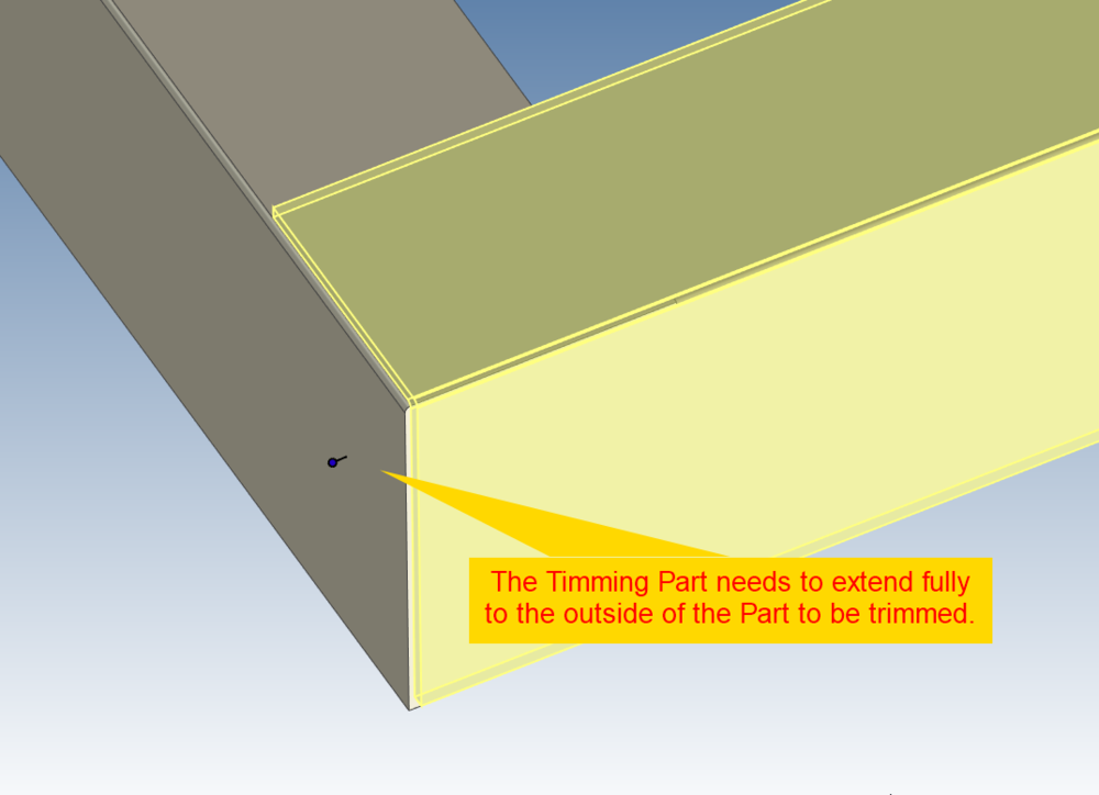
Hi tgjang, Have a look at the attached image and video and let me know if that helps solve your issue. Malcolm EndCut - 20230902.mp4
-
Hi Vendel, I realize that this isn't exactly what you're after, but it provides another option (adding to what Cary has already suggested). That is, to save your original Part files as "Master Part" files, and then create new "Part" files (as Structured Parts) that have a BREP feature in them that is linked to the original "Master" files. If you save these new files as the original file names, all of your linked Assemblies across your many projects will automatically start referring to these new child files (that can't be easily edited). This is demonstrated in the attached video. Something that isn't demonstrated in the video (but that's necessary) is copying the Part Properties from the Master Part to the newly created Child Part. This can be done easily using the Eye Dropper tool. Malcolm Creating Master and Child Parts.mp4
-
Combining Images, 2D Geometry and Generated Views (CAXA)
Malcolm Crowe replied to Malcolm Crowe's topic in Tips and Tricks
Attached is a video demonstrating how to combine 2D geometry (located in a Block) with 3D geometry (located in a Generated View) within "Model Space". And to then display this combined geometry within "Layout Space" at different view scales using "Viewports". This includes how to use the "Align" tool to perfectly position the 3D geometry on top of the 2D geometry, and how to "Pan" (position) the model within the Viewports. This is a good example of when to "Generate Views" within "Model Space" (instead of directly within "Layout Space). Malcolm CAXA - Model Space - Combining 2D and 3D Geometry.mp4 -
Questions about Structured modeling with Skeleton
Malcolm Crowe replied to tgjang's topic in General Discussion
Because Bodies use the Coordinate System of the Parent Structured Part, if the Body reorientates within the Structured Part, the BREP within any externally linked Part will also reorientate in the same way. So, yes it will affect the Generated Views within 2D Drawings. However, if you use "Define Front View Definition" within the externally linked Part, and generate your 2D Views using that, then that should no longer be a problem. See the attached videos. Note that when Generating Views, it's critical to select "Associate to Front View Definition". Malcolm Structured Parts - Creating Part Drawings of Individual Bodies.mp4 Structured Parts - Using Front View Definition.mp4 TERMINAL CRIMPER - Part Drawings - Part 2.ics TERMINAL CRIMPER - Part Drawings.ics -
Questions about Structured modeling with Skeleton
Malcolm Crowe replied to tgjang's topic in General Discussion
At the end of the demonstration video I add geometry to the Skeleton Sketch to provide "Shape Handles" for dragging the geometry using a mouse. So, you have the option to either drive the model using Parameters or to move it Freely with the mouse. -
Questions about Structured modeling with Skeleton
Malcolm Crowe replied to tgjang's topic in General Discussion
Hi tgjang, Attached is the promised demonstration video. I've also attached various *.ics files of the steps shown in the video. I've only demonstrated the construction of the Skeleton Sketch and the first 2 Parts. Hopefully this is sufficient to convey the principle. Malcolm Structured Parts with Skeleton Sketch.mp4 TERMINAL CRIMPER - Step 2b.ics TERMINAL CRIMPER - Step 2a.ics TERMINAL CRIMPER - Step 3b.ics TERMINAL CRIMPER - Step 3a.ics TERMINAL CRIMPER - Step 1b.ics TERMINAL CRIMPER - Step 1a.ics -
Combining Images, 2D Geometry and Generated Views (CAXA)
Malcolm Crowe replied to Malcolm Crowe's topic in Tips and Tricks
Attached is a video demonstrating how to scale an imported image (aerial photo), so that a known distance within the image measures correctly at a scale of 1:1 within CAXA. This is important, because we want to be able to combine the image (photo) with other 2D and 3D geometry. After scaling any image to the correct size, I recommend defining it as a "Block" (and include any other desired 2D geometry to help with dimensioning, locating, etc.). When the "Block" is created, it is created with a scale of 1:1 (which is what you want). When this "Block" is then inserted within a layout, the "Block" can be scaled (using the Properties Browser) in the same way that a Generated View is. Malcolm CAXA - Inserting and Scaling Site Images.mp4 -
Questions about Structured modeling with Skeleton
Malcolm Crowe replied to tgjang's topic in General Discussion
Hi tgjang, I'm pleased that you made the effort to construct this, and congratulations on creating a Multibody Structured Part. Where you went wrong was that the very first feature needs to be your Skeleton Sketch (Layout Sketch). From there you then want to create a separate Sketch for each of the Parts, with each of these Sketches being associated to the Skeleton Sketch (and if necessary, any other Part Sketch before it). Then, you use these Part Sketches as the basis for constructing the solid bodies. This is explained in the attached video, but I'll create a separate video for you shortly demonstrating how to associate these separate Part Sketches to the initial Skeleton Sketch. So that everything follows any changes made to the Skeleton Sketch. Malcolm Comments regarding Termianl_Crimper-Skeleton-1.mp4 -
Questions about Structured modeling with Skeleton
Malcolm Crowe replied to tgjang's topic in General Discussion
Hi tgjang, Below is a link to a forum post that is a better place for you to start (rather than the Academy), as the videos and documentation in the forum post were created specifically for beginners to Structured Parts (whereas the Academy videos weren't). This post doesn't specifically demonstrate what you want to do with Sketches, but you need to understand the basics. Malcolm -
Questions about Structured modeling with Skeleton
Malcolm Crowe replied to tgjang's topic in General Discussion
Hi tgjang, I've just watched the video (as I was curious regarding PTC). The design process demonstrated seemed more complicated than is necessary with Structured Parts in IRONCAD. So, I don't recommend strictly following the methodology demonstrated in the video. What PTC describes as "Skeleton Parts" we (my company specifically) refer to as "Layout Sketches". We use "Layout Sketches" all the time for controlling the size and positioning of Parts. So, I understand the concept very well. However, there are a couple of different ways that this can be approached using Structured Parts. 1. Is to duplicate the process demonstrated in the PTC video. That is, with a separate "Skeleton Part" driving separate linked "Parts". 2. Creating all of the "Parts" as associated "Bodies" within a single "Master" Multibody Part. The principle of driving the size and position of everything from a "Layout Sketch" (Skeleton Part), remains the same for both options. In your attached file you have 2 Innovative Sketches that have no Projected Constraints between them. So, there is no association between the sketches. You have to understand how to use "Projected Constraints", as they are the basis of everything that you'll be doing within Structured Parts. Malcolm -
How do I change line lengths in CAXA Draft?
Malcolm Crowe replied to tgjang's topic in General Discussion
Hi tgjang. In the attached video I demonstrate the 3 methods that I'm aware of. 1. Stretch Handles (Triangle): Note the settings within "Options" regarding Relative and Absolute. Also ensure that "Dynamic Input" (bottom right) is turned off. 2. Stretch Command: Use the "Single Select" option in the bottom left corner. 3. Dimension Drive: Temporarily enables you to drive geometry using the associated dimensions. Malcolm CAXA - Stretch Handle, Stretch Command, Dimension Drive.mp4 -
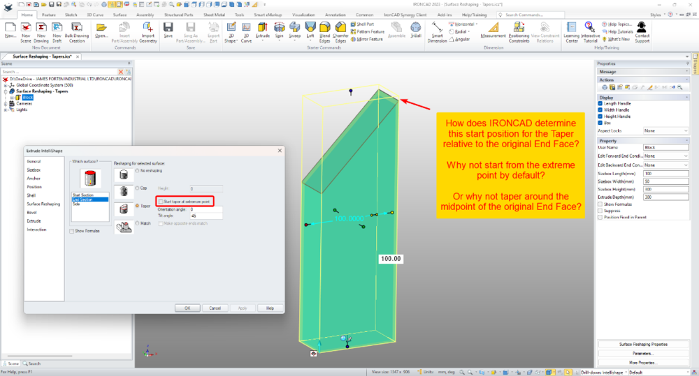
Something that I've never understood, is how IRONCAD determines the default "Taper Start Position" when using Intellishape Surface Reshaping. It seems completely random or illogical to me; and I don't see how this default position is useful at all. Is someone able to enlighten me? I've read the "Help" material regarding this, but I don't find the description to be helpful. Malcolm IRONCAD - Intellishape Surface Reshaping - Taper Start Position.mp4
-
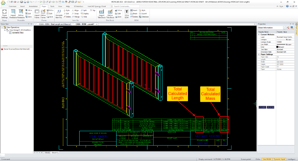
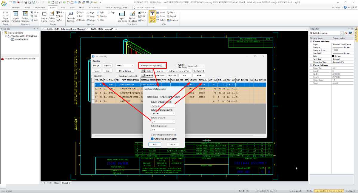
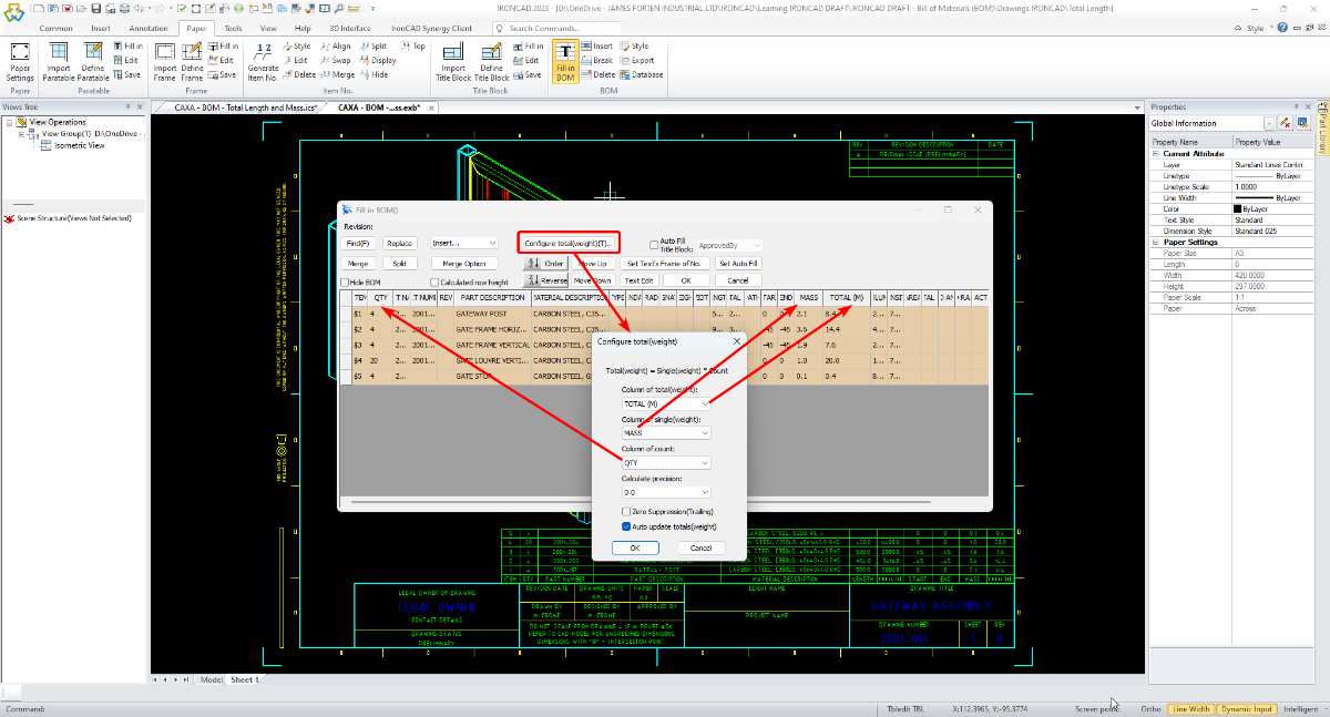
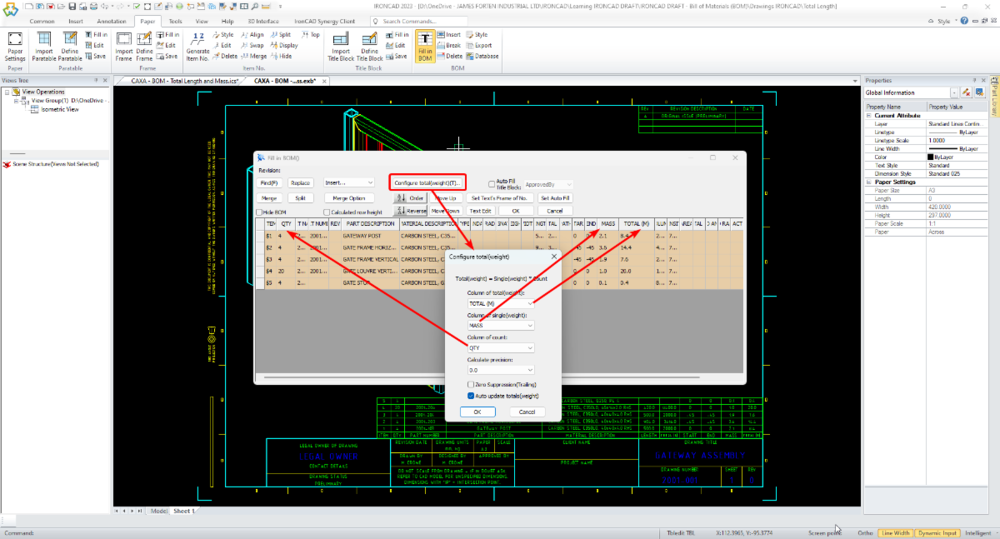
CAXA - BOM - Calculating Totals (length, mass, etc.)
Malcolm Crowe posted a topic in Tips and Tricks
The attached video demonstrates how to add columns within a Bill of Materials (BOM) in CAXA, for calculating the Total Length and Mass of items. While it isn't obvious, it is possible to have multiple "Total" columns within a single BOM; however, it's important to be aware that only one of the "Total" columns will automatically update following changes to the 3D Scene. This is demonstrated in the video. Malcolm CAXA - BOM - Total Length and Mass.mp4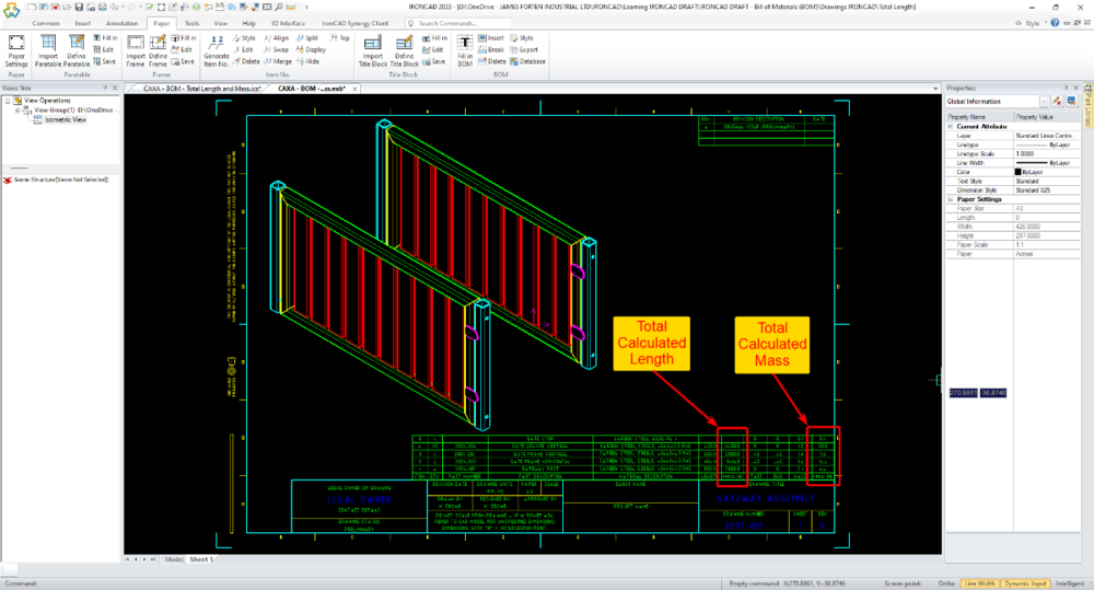

-
Hi Sarath, I realise that you were specifically asking regarding ICD, but CAXA has this Weld Bead capability. The attached video starts with demonstrating how to create Stacked Weld Symbols in CAXA, but from around the 1:37 mark, the video then demonstrates the Weld Bead tool in CAXA. Malcolm CAXA - Weld Beads and Stacked Welding Symbols.mp4
-
Because we create a lot of Parametric Parts, we try to be consistent in how we construct and manage Parameter Names (regardless of who is creating the model). The naming conventions that we've used over the years have varied, but for those who are interested attached is our current internal document defining how our Parameter Names are to be constructed. Malcolm IRONCAD - Parameters - Name Construction - 20230708.pdf
-
For those interested in learning how to achieve the same end result in CAXA, see the forum post at the link below. Malcolm
-
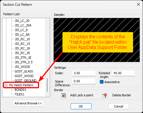
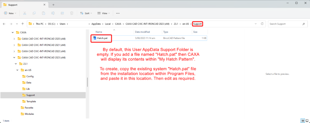
By default, CAXA includes a comprehensive list of Hatch Patterns that are available for both 2D and 3D hatching. However, it's possible to add other Hatch Patterns from other DWG Editors (including AUTOCAD), without the need to create them yourself. This is done by adding a "Hatch.pat" file within your User AppData CAXA Support Folder. Then within this file, either paste the desired contents from other *.pat files, or manually write the Hatch Code (if you understand how to do this). This is demonstrated in the attached video. Malcolm CAXA - Adding Hatch Patterns.mp4
-
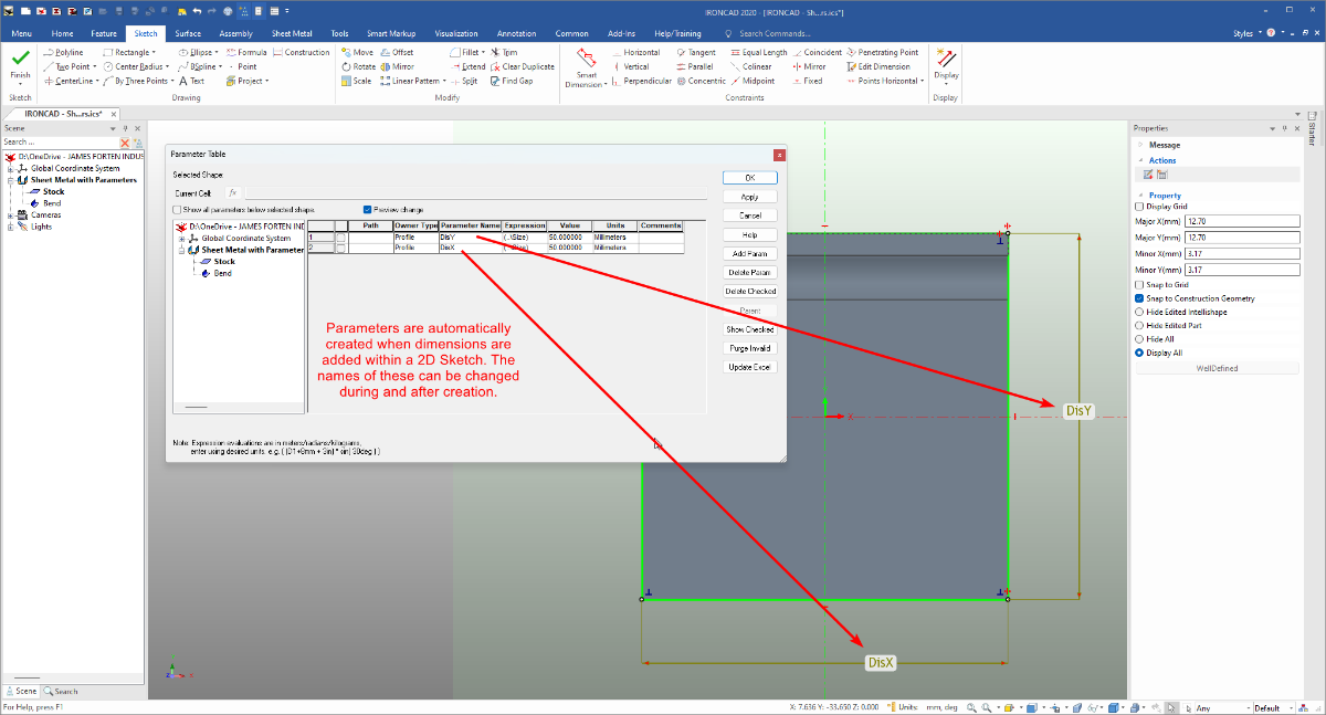
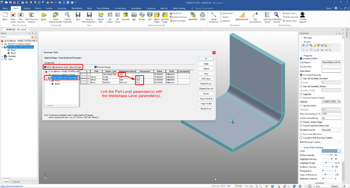
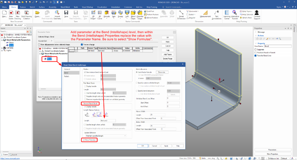
For those wanting to create Parametric Sheet Metal Parts, the attached video demonstrates how to apply these within the 2D Sketch of Stock, and within the Intellishape Properties of Bends. I’ve also attached some images and the 3D file from the demo. This was created specifically for another user (in IC2020), but I thought other users might have a similar interest (or need). Malcolm IRONCAD - Sheet Metal with Parameters.mp4 IRONCAD - Sheet Metal with Parameters.ics


-
CAXA: 1:1 DWG Model file I need to get to A1 paper
Malcolm Crowe replied to HDEAR's topic in General Discussion
Hi Harley, A demonstration video has been sent to you, based on what I described above (Paper Settings in Model Space). Malcolm -
CAXA: 1:1 DWG Model file I need to get to A1 paper
Malcolm Crowe replied to HDEAR's topic in General Discussion
Hi Harley, Has this drawing been fully dimensioned within "Model Space"? If that is the case, it might be best to use "Paper Scale" within "Paper Settings" to resize your Client's drawing Frame and Title Block to fit around what you have received (all within Model Space). If the drawing wasn't fully dimensioned in Model Space, I would recommend using a "View Port" (with a reduced View Scale) in "Layout Space" (at the normal Paper Scale of 1:1). Email me the DWG if you want me to check. Malcolm