Malcolm Crowe
-
Posts
1,760 -
Joined
-
Last visited
Content Type
Profiles
Forums
Blogs
Downloads
Articles
Gallery
Everything posted by Malcolm Crowe
-

Attachment Point Connector - Default APs Limit Selection
Malcolm Crowe replied to Malcolm Crowe's topic in General Discussion
Thanks Kevin, that's good to hear. Malcolm -
Can I Add color at the assembly level only
Malcolm Crowe replied to PWATSON's topic in General Discussion
Hi Peter, The weather hasn't been favorable for cycling (one of my fun things to do), so I've been working today. It helps that my wife is away working this weekend as well. Attached is a video that I hope demonstrates well enough what is possible with "Design Configurations" and "Scene Configurations". I've also attached the Scene files used in the video. One of the great things about "Design Variations" is that they are saved with the Part (or Assembly), and not with the Scene. As a result, "Design Variations" are saved with the Part (or Assembly) when dragged into a Catalog. This is not the case with "Scene Configurations" (which are Scene specific). Malcolm IRONCAD - Design Variations - Applying Colors.mp4 ASSEMBLY.ics PIE.ics PYRAMID.ics SPHERE.ics SUB-ASSEMBLY.ics -
Can I Add color at the assembly level only
Malcolm Crowe replied to PWATSON's topic in General Discussion
Hi Peter, If you're using externally linked Parts that are inserted into Assemblies, then the following might work for you. However, you need to be aware, that it's not possible to have different colors for the same Part within the same Scene. "Design Variations" allow you to assign specific colors to each DV if wanted. So, for your Parts you could have "Painted" and "Unpainted" DVs. Then when you insert one of these Parts within an Assembly, you could use "Add to Active Configuration" within the "Design Variation Dialog" to link the desired DV of the Part (Painted or Unpainted) to the current Configuration of the Scene (into which it has been inserted). Let me know if this doesn't make sense, as I can potentially make a video in the weekend. Malcolm -
This is an example of how to combine multiple Imported Parts (whether Innovative or Structured) into a single Part using the "Copy Body" tool. Malcolm Copy Body - Combining Multiple Parts into One.mp4
- 1 reply
-
- 3
-

-

-
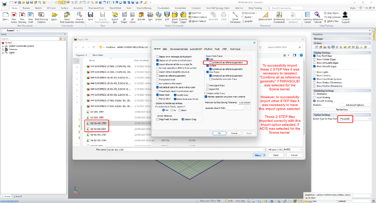
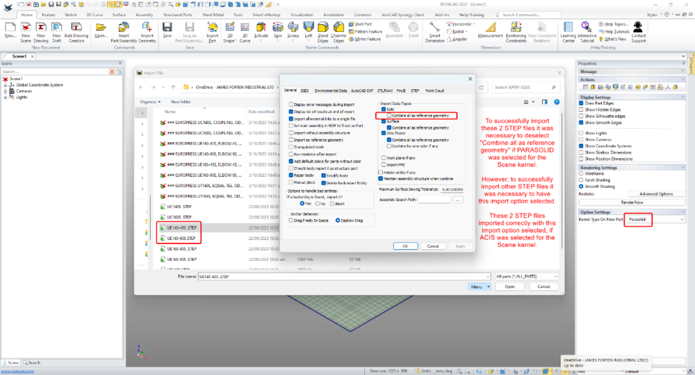
This example involves the importing of a couple of *.stp files that behaved differently compared to other *.stp files received from the same manufacturer. To successfully import these particular files, it was necessary to either change an import setting (Combine all as reference geometry), or to change the Scene kernel from PARASOLID to ACIS. Malcolm IRONCAD - Importing STEP Files - Comparison of Settings.mp4
-
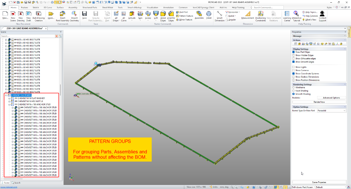
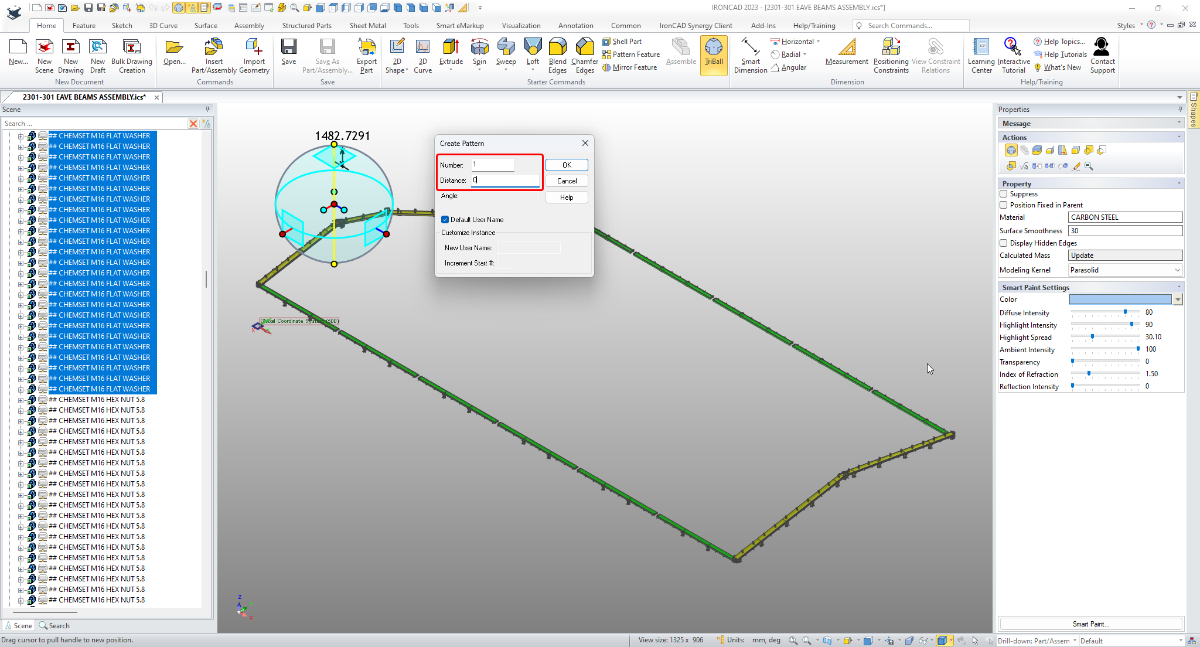
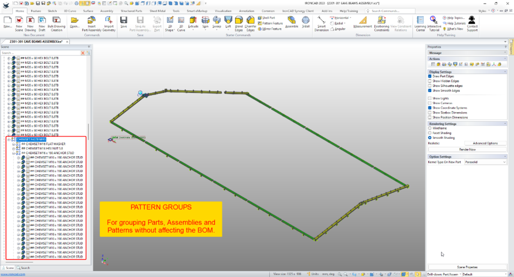
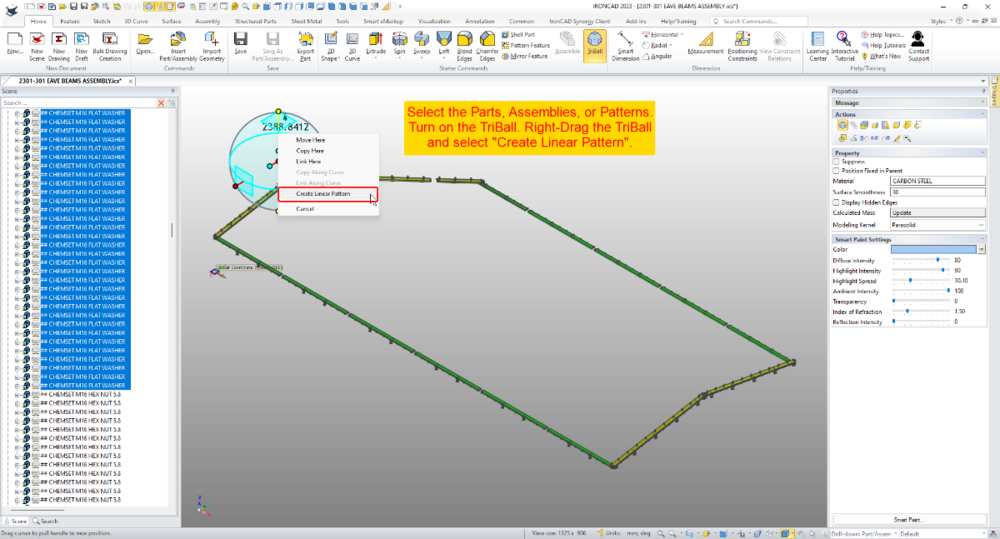
I use the term "Pattern Group" as a Group (of Parts, Assemblies or Patterns) created using the "Linear Pattern" tool of the TriBall; where the pattern number has been set to "1" and the distance to "0" (zero). "Pattern Groups" are extremely useful for simplifying the assembly structure within the Scene Browser, without affecting the BOM (which would be affected if an Assembly was used). The attached video demonstrates how this can be used for grouping hundreds of fasteners to greatly simplify the assembly structure, without affecting the BOM in the associated 2D Drawing. It also includes placing Pattern Groups within other Pattern Groups. Malcolm IRONCAD - Pattern Groups - Alternative to Assemblies and Groups.mp4

-
CAXA - PDF Import (converting PDF into CAD geometry)
Malcolm Crowe posted a topic in Tips and Tricks
Recently I needed to create some 3D models from PDFs received from a client. These PDFs didn't include all of the dimensional information needed, so I was grateful to have at my disposal the "PDF Import" tool within CAXA (not to be confused with the "Insert PDF Underlay" tool). The "PDF Import" tool converts PDFs into CAD geometry (which is what I needed). Attached is a video demonstrating how this works. The PDF used in the video was originally created in CAXA, and the original "Layers" from the CAXA drawing were saved within the PDF. During "PDF Import" these same layers are again imported back into CAXA. Depending on what print driver (or software) created the PDF, "Layer" information may not be available. Malcolm CAXA - PDF Import.mp4 -
NOT including all parts in a scene from being included in BOM
Malcolm Crowe replied to HDEAR's topic in General Discussion
Hi Harley, You need to be careful when deselecting "Include in BOM" as it will affect any 2D drawings or scenes referencing those parts. See the link below. I personally would create a new "Configuration" in which everything is suppressed, apart from the items that you want to appear in the BOM. Then reference that specific "Configuration" in your BOM within CAXA. Malcolm -
CAXA - Broken out section on isometric
Malcolm Crowe replied to PWATSON's topic in General Discussion
Hi tgjang, I just used that old example because I knew it had many Sectioning Configurations already setup in it; but I don't consider that model to be complex compared to other work we do. For that particular project we needed to create a 3D model of an existing Multi-Storey Building (over 100 years old), so that we could then add various new Structural Elements for Earthquake Strengthening purposes. So, it doesn't include all of the details (such as steel reinforcement and connection details) that would have been needed for constructing the original building. We only needed to add details for what was to be added for strengthening. If you're curious regarding the types of structural drawings produced in CAXA from this 3D model have a look at the attached PDFs. Malcolm W140507c-S11-S19-BC1 Plan Sections.pdf W140507c-S21-S32-BC1 Southern Sections.pdf W140507c-S41-S44-BC1 Western Sections.pdf W140507c-S51-S60-BC1 Strengthening Details and Pile Cap.pdf -
CAXA - Broken out section on isometric
Malcolm Crowe replied to PWATSON's topic in General Discussion
Hi Peter, To my knowledge, the Section and Broken-Out Section tools don't work with Isometric Views. To achieve any type of Sectioned Isometric View in CAXA we create the desired section in a specific "Configuration" within the 3D Scene, that we can then select when generating the View. The principle is demonstrated in the attached video. These sections can be created using the "Section" tool, or by using "Assembly Features" (necessary for Broken-Out Sections). Malcolm CAXA - Creating Sectioned Isometric Views.mp4 -
Crreating Real Threads very eazy with Catalog
Malcolm Crowe replied to Bertrand Kim's topic in Tips and Tricks
Hi Kim, That's a good tip! Thanks for sharing. Malcolm -
Attachment Point Connector - Default APs Limit Selection
Malcolm Crowe replied to Malcolm Crowe's topic in General Discussion
Thanks Cary and Kevin. I'll carry on setting "Default" APs at both ends with the hope that this will be fixed in the near future. Malcolm -
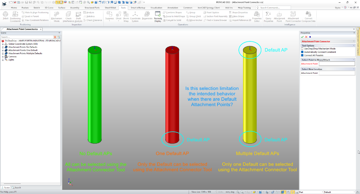
When using the Attachment Connect Tool, the presence of "Default" Attachment Points limits the selections available to the user. If there is one "Default", then only that "Default" AP is available for selection. If there are multiple "Defaults" then IRONCAD will only make one of them available for selection. See the attached video. Is this the intended behavior or is this a bug? I like to use "Default" APs when dragging and dropping from catalogs (to minimize having to use the right-drag selection option). However, I don't like the limitations "Default" APs impose when using the Attachment Point Connector. When using this tool, I'd like to be able to select all AP options. Malcolm Attachment Point Connector - Default APs Limit Selection.mp4 Attachment Point Connector - Default APs Limit Selection.ics

-
Attachment Point Connector - Doesn't Connect Clusters
Malcolm Crowe replied to Malcolm Crowe's topic in General Discussion
Thanks Kevin (and for the QA reference). Malcolm -
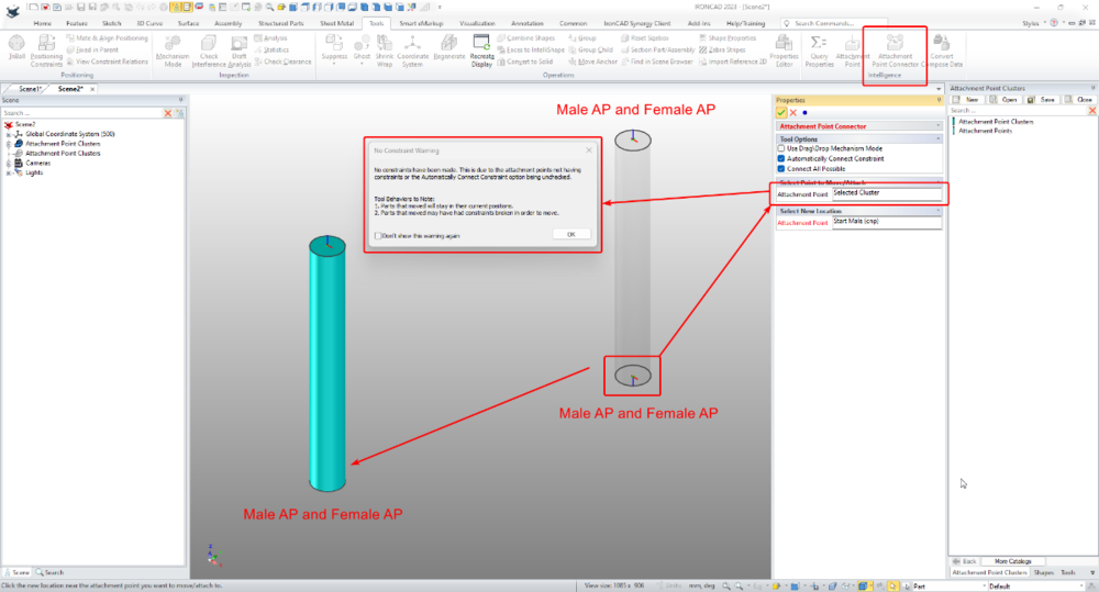
I'm trying to use the "Attachment Point Connector" with Parts that have Attachment Point "Clusters" (that is, multiple Attachment Points in the same location). However, I'm unable to get it to work. Attached is a video of my process, along with the ICS file. 1. Am I doing something wrong? 2. Is this simply a limitation regarding the Attachment Point Connector? 3. Or, is this a bug? Malcolm Attachment Point Connector - Doesn't Connect Clusters.mp4 Attachment Point Clusters.ics
-
BOM - Exported to Spreadsheet (CAXA)
Malcolm Crowe replied to Malcolm Crowe's topic in Tips and Tricks
-
Can I use Pitch of thread as Parameter Expression?
Malcolm Crowe replied to Bertrand Kim's topic in General Discussion
Hi Kim, The link below might be of interest, as it's regarding Requested Enhancements for the Thread Tool. The includes the ability to use Parameters within the Thread Feature Properties. Malcolm -
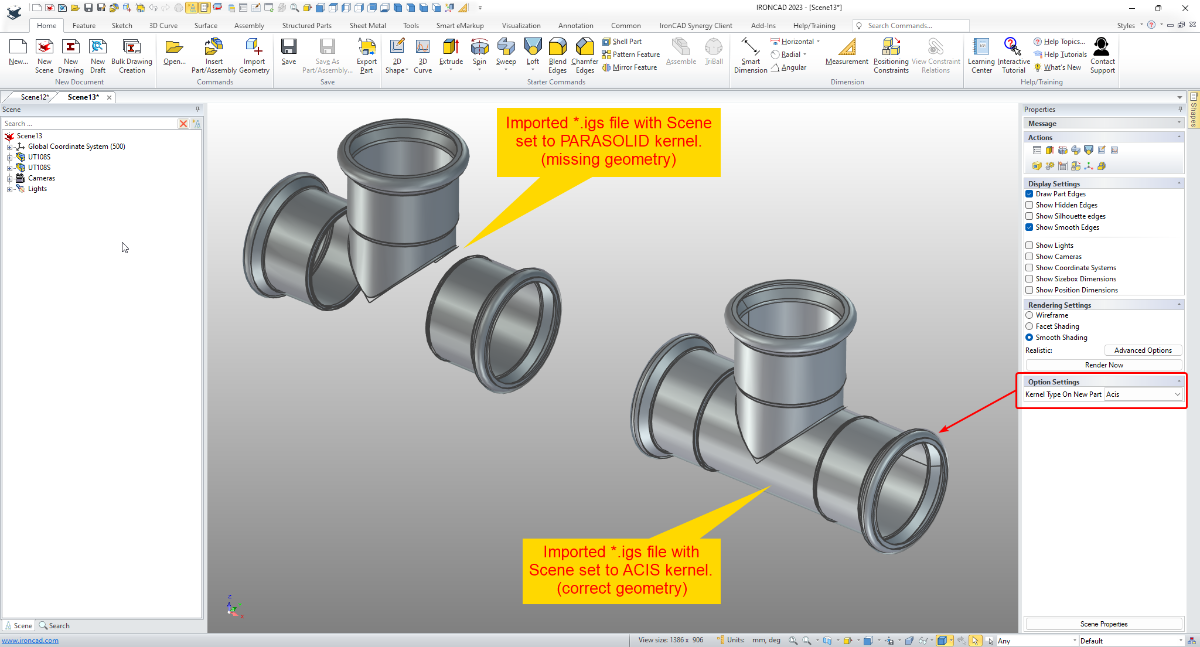
The attached video is an example, where having Dual Kernels helped when importing a particular group of *.igs files. IRONCAD failed to import all of the geometry when the Scene was set to the PARASOLID kernel, but successfully imported all of the geometry when the Scene was set to the ACIS kernel. Malcolm IRONCAD - Dual Kernels - Importing IGS File - 20230914.mp4

-
Hi Kim, The top distance relates to the thread depth. The bottom distance relates to the hole depth. In this case, the thread length of the Hole Feature is the same as the hole length, so they appear to be a duplication (but they aren't). You can manually edit the cell afterwards if wanted (like other tables). See the attached video. I'm not aware of how to change the style of these Hole Lists (if that is what you want), but maybe someone else does. Malcolm CAXA - Auto Hole List.mp4
-
CAXA - Can I edit the automatic value of Dimdistance?
Malcolm Crowe replied to Bertrand Kim's topic in General Discussion
Hi Kim, When you select the "Automatic" option of the "Distance Between Dimensions" tool, then CAXA will set a distance of 3 times the text height of the dimension. So, if the text height is 2.5mm it will set a distance of 7.5mm. I'm not aware of any way to change this "3 times" factor used by "Automatic". If you want a smaller distance (such as 2 x the text height) then you need to select the "Manual" option and then set the desired distance (such as 5mm). See the attached video. Malcolm CAXA - Distance Between Dimensions.mp4 -
Single line font for laser profiling of part numbers
Malcolm Crowe replied to dbarber's topic in General Discussion
Hi Dave, An alternative to Single Line TrueType Fonts (*.ttf) is to use Shape Fonts (*.shx), which are all genuine Single Line Fonts. However, you need to be aware that IRONCAD's 2D Sketch and Drawing (ICD) don't work with Shape Fonts. They are limited to whatever TrueType Fonts are installed in the Windows\Font directory of your PC. CAXA on the other hand can use both TrueType and Shape Fonts. Depending on how you generate your DXFs you have the following options: 1. Create split faces on your 3D part, using a 2D Sketch in combination with the Split Face tool. The disadvantage of this approach is that Split Faces are lost when you unfold a sheet metal part. So, this option isn't the best for sheet metal parts (we know this from experience). 2. You create the desired etching (which can be text and lines) as a 2D Sketch, and then project that 2D Sketch along with the Solid Geometry within your Generated Views in CAXA (or ICD). We've used this approach many times when we want to etch lines for the positioning of other parts during fabrication. This would work for text also, but the next option is easier. 3. Simply add the desired text (using a Shape Font) to the Generated View within CAXA, before saving as a DXF. If you choose to use a Shape Font (*.shx), this will need to be saved in the folder that CAXA is looking at for its fonts. CAXA includes 4 Shape Fonts within its Program Files which will automatically list within your font options, but these fonts are specific to CAXA (so won't be recognized by other software unless they add them). I suggest that you use a Shape Font that is commonly installed within other CAD software (like AUTOCAD and other DWG Editors). An example being isocp.shx (which I have attached here). Finally, if you ever want to use a Shape Font within an IRONCAD 2D Sketch, you need to create the text in CAXA first (using the desired Shape Font). Then you need to "explode" the text, using the Explode tool. This converts the font characters into simple geometry, that can then be easily recognized by the 2D Sketch during importing. Malcolm isocp.shx CAD - Fonts - 20230911.pdf -
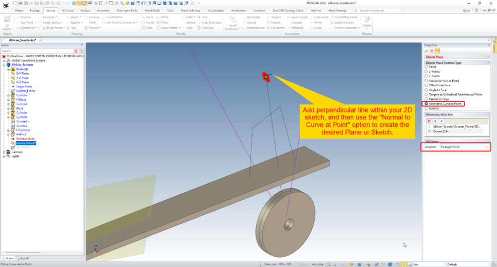
Hi tgjang, It's possible to achieve the end result that you're asking, but just not in the way that you're asking. You need to add a perpendicular line within your 2D sketch, and then use the "Normal to Curve at Point" option. We often add these lines to our 2D sketches for this purpose. See the attached video. When using this option, I recommend selecting the "Point" first, and the "Curve" (line) second. Malcolm Datum Plane - Normal to Curve at Point.mp4
-
Hi tgjang, The attached video demonstrates the methodology that you need to use to attach the ends of 3D Curves to points in your 2D geometry (without additional 2D Sketches or Coincident Constraints). Basically, after creating the 3D Curves, you need to drag the ends away and then place back onto the desired points. Take care that you aren't attaching to the original point of the 3D Curve (as demonstrated in the video). Malcolm IRONCAD - Attaching 3D Curves to 2D Sketches.mp4 3D_Curve_Constraint - MC.ics
-
This video specifically relates to the "Parallel Capture Tool". This is enabled when using the "Guide Capture Mode". Malcolm CAXA - Parallel Capture Tool within Guide Mode.mp4
- 1 reply
-
- 4
-
-
-
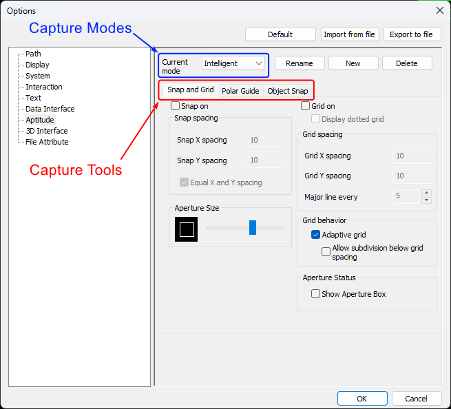
CAXA provides some really helpful tools to assist with selecting and creating geometry. The attached video and document provide an overview of these "Capture Tools" along with the associated "Capture Modes". When editing "Capture Tool" options it's important to be aware that these changes are only applied to the currently selected "Capture Mode". Malcolm CAXA - Capture Tools and Modes.mp4 IRONCAD DRAFT - Options - Aptitude (Capture Modes) - 20230905.pdf
- 1 reply
-
- 4
-
-