Mike Hatch
-
Posts
162 -
Joined
-
Last visited
Content Type
Profiles
Forums
Blogs
Downloads
Articles
Gallery
Everything posted by Mike Hatch
-
Have noticed that there are differences between an on screen view and a printed copy. On screen - Printed - Four tapped holes are showing ?. There are similar tapped holes in the side plates that don't show as artefacts, dimensionally they are all the same in the same thickness material.
-
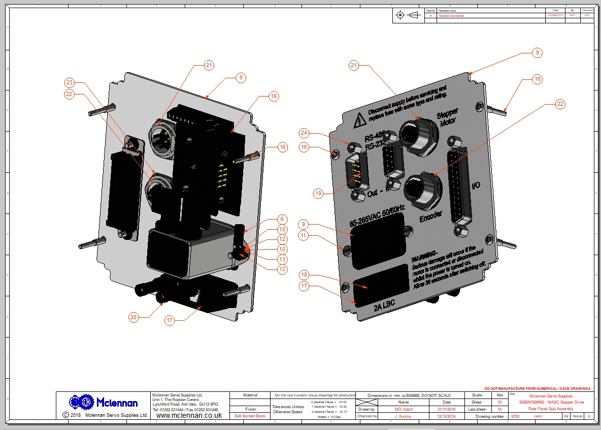
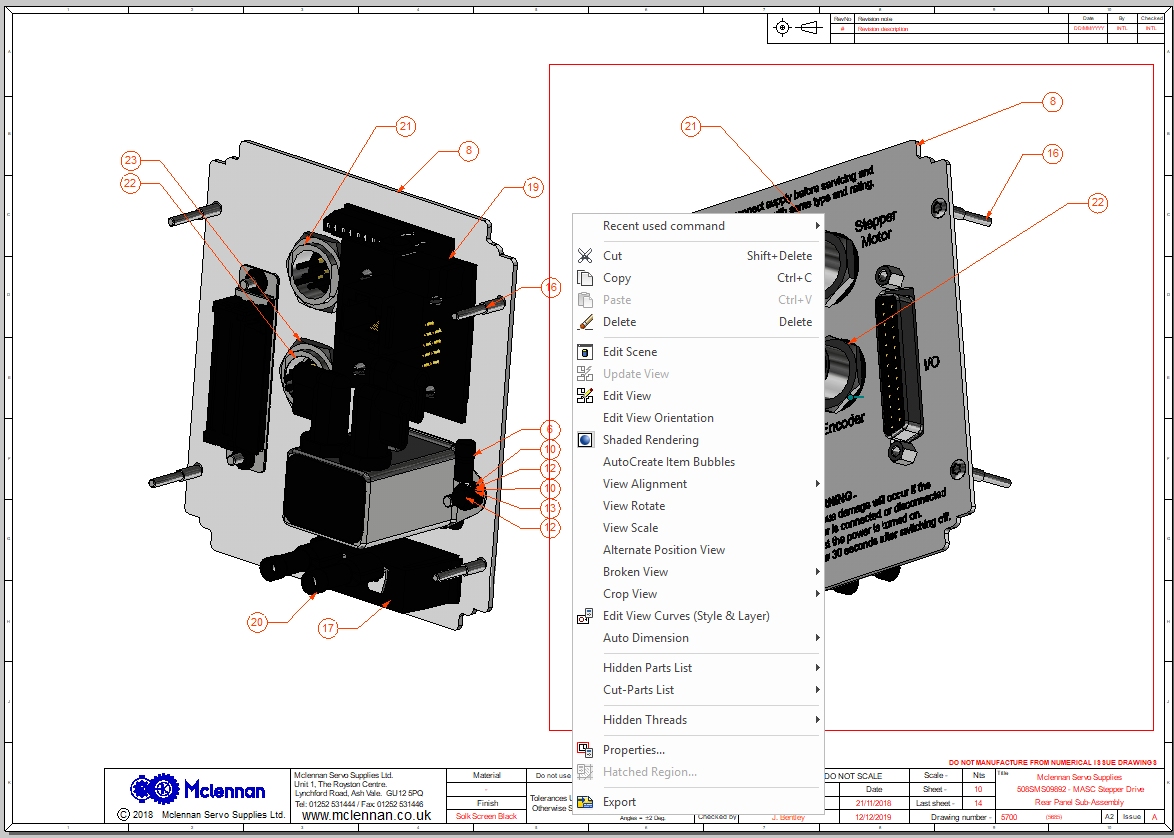
We normally have it set to Draft, up to IC2018 this has worked well for us. Not so with 2019. Attached image - - the left side is set to Quick, the right to Precise. Quick is better but there is still a large portion in shades of grey. Precise just shows outlines ???

-
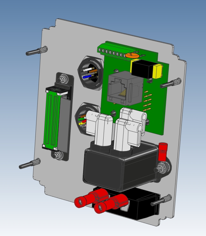
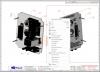
From a quick look at the files this morning it seems that surfaces that have had a treatment applied from the "Metals" catalog correctly render. This seems to explain why bits of the view are ok whilst the the rest is shades of grey. Applied colours (from the colour catalog) are black, applied treatments from the "Plastic" catalog are black. EG - Item 19 in the attached image is a green PCB, with yellow capacitors, orange disc fuse, grey RJ11 connector, gold pins on the rear of a D9 connector. - Only the gold pins and the metallic leads of the fuse show, the remainder is black. Items 21 & 22 have multiple coloured wires all are balk but the gold metallic pins show. Whilst discussing "shaded rendering" is there a reason that "Update View" is greyed out for view options with a shaded render ? needing to turn it off and back on to update the view.

-
It would be nice if - Up/down keyboard arrows scan through intellishapes, highlighting each (I.E. the old behaviour) Right arrow key - enters the intellishape, editing the X,Y & Z sizing. Esc - exits the X,Y & Z sizing, back to the scene browser.
-
Hi, I left the files for download by IronCAD as they totaled 140Mb. I had this email from Blake Staff on the 11th. ----------- Mike, We downloaded the files, and see the same differences in the shaded renderings. R&D will take a look at this, and we will let you know when we have new information available. Best regards, Blake Staff Support Eng. IronCAD 2000 RiverEdge Parkway Suite 745 Atlanta, GA 30328 P: (678) 909-3302 E: bstaff@ironcad.com W: www.ironcad.com --------- Let me know if you need them again. mike.hatch@mclennan.co.uk
-
Kevin. Is there any news on the "black" shaded rendering problem in IC2019 ? Mike.
-
Yes if you look directly (perpendicular) at a surface the triball will show correctly that perpendicular aspect, so you will have to move slightly. You can "look at" (F7) on the same plane and pick slightly offset, the view will shift and re-orientate the triball, but then that's just similar to your spinning slightly off axis I don't have 2018 any more to try this out, do you have an example (picture).
-
A new “feature” - Quick Feature Size Editing on Starter/Shapes Catalogs, allows to drop an intellishape and directly edit the size, X,Y & Z if - Automatically switch to next sizebox handle – is on. Unfortunately this has broken the ability to rapidly scan through intellishapes in the scene browser. On parts with a large amount of intellishapes it used to be possible in IC2018 to be able to select a part in the scene browser and then use the up or down keyboard keys to scan through and find an intellishape buried in a part of many intellishapes. There does not seem to be a switch in the options to turn this off. It would be nice if on dropping an intellishape you could immediately edit the sizing, but if you select it in the scene browser that option is not used.
-
We use both, probably 90% IronCAD, 10% Caxa Draft, with a caveat. We have a large archive of AutoCAD 2d drawings going back 35+years for product still in the field, still manufactured and supported (Science industry) so we regularly use CAXA Draft for the archive, its similarity to AutoCAD makes it a breeze. In 2009 we went over to IronCAD having evaluated several packages and never looked back. All new projects are IronCAD but CAXA Draft has its place, not for new projects though.
-
Sorry to hijack your post as I'm afraid I can't help, but comment on the problem of new IronCAD updates. Hopefully Kevin will take note. New installs and IC2019 is due soon, do seem to loose any special key setups and menu configurations, selections and positioning, happens for us each year, we have to go and update the new install to match the previous one. It might be simplistic but is it not possible for the new install to interrogate the previous, gather the users settings and then apply them. I have other programs that do precisely that making an update a painless process. We love IronCAD but the yearly update/install is a bugbear for such a good package. We have mentioned it to our reseller, who I'm sure has passed it on, and I know its relatively minor for a hour or so's pain, but please it should be so simple.
-
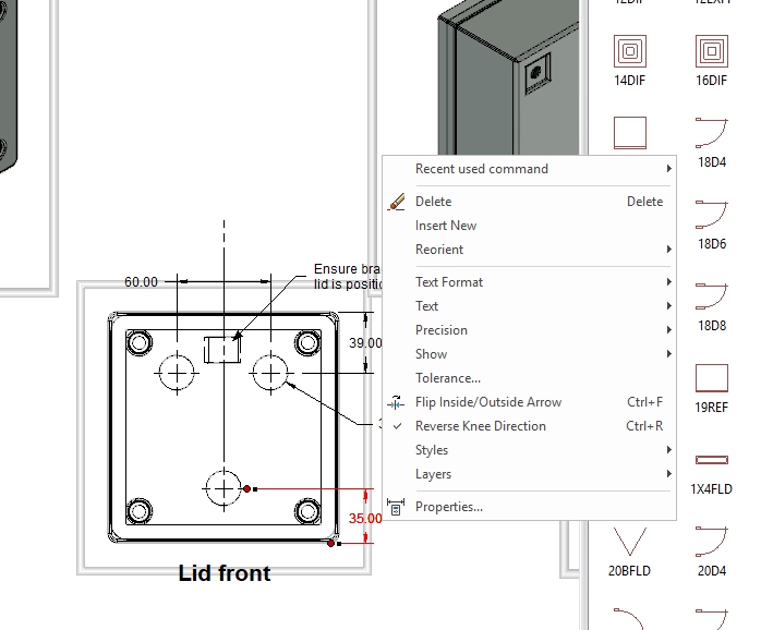
Select the dimension to highlight it (red), right click and you get a popup with all the options available. Select - Flip Inside/Outside - to place the arrows inside or outside the dimension lines. Reverse knee direction - to swap the direction of the dimension to the line. Text - gives you further options for pretext, post text, font, size, arrow size, dimension style (ansi, iso) and lots more. To line up dimensions click the point where an arrow meets its dimension line (cursor becomes a hand) and drag it to another similar point, a green dot will appear when snapped, the original dim does not change just realigns with the snapped dim. If placing radial or diametral dims click the arrowhead (hand again) and drag it around the chord to place it, click the dimension and drag it in or out. Right click when selected to again get to the properties.
-
Yes. It is happening to us quite regularly since we installed 2018 SP1 not seen on 2017. I can have a number of catalogs opened during use and they work fine, finish the job and close down. Next time IC is loaded all the catalogs may or may not be there, or some may be there with others missing. Not found any defining factor yet but could be related to adding a new item to a catalog, re-arranging it and closing down. All our catalogs are local to the machine, not on the cloud or a server. Registry Key HKEY_CURRENT_USER\Software\IronCAD\IRONCAD 20.0\LangDependent\en-us\Scene attached here. Mike scenecatalogs.zip
-
Fine for me, scene and browser. IC 2018 SP1 64bit 15558,Win 10
-
Any examples to show us ?. I do find that the print preview in IronCAD sometimes does not quite match the printed result on paper (some text boxes truncate) but its very minor and usually it works fine for us. Are you generating from within IronCAD or using an application ?. We use a free print utility - PDF Creator - (https://www.pdfforge.org/pdfcreator), it shows up in your list of printers once installed so works on all sorts of programs. Used it for years and gives us what we want. It will try to install - PDF Architect - during the creator install, just be careful of the tick boxes and the "no thanks" button and this won't happen.
-
Thanks
-
I saw an IronCAD video recently where available commands appeared as a "halo" circle of icons around a point (different triball ?). Was that a new item or from a very old version of IC. Unfortunately I cannot remember where I saw it.
-
IC 2017 and 18 seem to be fine under Win10 and much faster too, for us some of the minor niggles seem to have resolved, although disappearing item #'s in a BOM box on icd files is still with us.
-
As we do not use the inbuilt pdf export this is an alternative. We use a free external pdf utility (PDF creator) output as 'File-print' rather than 'rightclick-export-pdf'. As its set up as a printer selection it works with all of our other apps as well. http://www.pdfforge.org/pdfcreator - Its licensed for work and home usage, just watch out at installation and at update time for the confusing tick boxes trying the get you to load PDF Architect, a cost item.
-
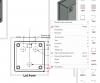
The ICD drawing should be linked to an ICS model file, within that model you have to set up "configurations" (views) of the model to match your required view and BOM on the icd drawing. For each configuration you set up, select the parts you - DO NOT - want and "suppress" them, either from the view or the scene tree. In the linked ICD drawing, views that need updating to the model configuration will have a thick grey box around them, left mouse click within that grey box, it will add a thin red outline, right click and select "update view", the drawing will reflect the .ics configuration. A BOM table works the same way. You will get into a cycle of editing the model, updating the icd, editing the model, updating the icd. It will resolve in the end. Each part of the 3d model has an "assembly property" (right click select "assembly properties") where you set if that part is included in the BOM, and give it a part # and description that appears in the BOM table, also if the part is treated as a unique part or expanded into multiple parts. If you have blank lines you have parts that need to have their properties set up or be disabled. Finding these blank line parts can be a real pain the the rear, and there seems to be no indicating mechanism to help in finding them (help here please if anyone knows how) although I find the part in the preceding complete line is a good place to start looking. 1) An ICD file can have only one BOM table if you have multiple sheets in that file, however you can cut and paste the original BOM table to another sheet if you need it. 2) There is a bug in updating a BOM table where the item #'s disappear, you'll have to edit the table or reload it. This happens to us on multiple workstations. 3) Part #'s determine an item's qty in the BOM table, the description does not. If you have just started using BOM's in ICD files you may need to invest some time in updating your ics models so that the assembly properties are correctly set up, until then you will see blank lines in BOM tables, once done though it is a very useful feature. It helps to correct and set up everything first and then update table last, previous item bubbles placed will track the updated BOM table. Apologies for the long post and repeating what many will already know. I'm open to any corrections or easier methods.
-
Can you put the model file (.ics) on here so we can have a look. I have found that if you want to measure its better to pick a face of the axis rather than the edge.
-
2D Shape Sketching in Center of Assembly/Part
Mike Hatch replied to DRAFFERTY's topic in General Discussion
You can hide and un-hide parts, you can suppress and un-suppress parts, you can select an individual face and change its transparency, you could drop a surface onto a face from the glass catalog, I'm not sure if any of these give you what you want though. For me hiding and suppressing has always done what I needed when sketching in large assemblies, I don't believe you can change the hiding one a sketch has been started though. I'd also be interested to know if there is a single key type of "cut away" function as you describe in Catia. Mike. -
Hollow (H) shapes will only work on solid items if they are under the the same "part" in the scene browser.
-
Hi, It’s the old rule - K.I.S. Regardless of sheet metal or machined parts, one item per sheet. First sheet = main assembly, BOM table, top level drawing #. Subsequent sheets = individual parts (or sub-assemblies) and sub level dwg# per sheet. Ironcad ICD drawing s allow you to set properties for the drawing that populate through multiple sheets of a drawing. (File - properties - IronCAD or IronCAD Custom) Each to their own though, this is my way, others most certainly will work differently. Mike.
-
I don't see that folder either - C:\Program Files\IronCAD\2016\AppData\en-us\FastenerData\ANSI_English\Bolts\ however it does exist within the file - FastenerData.zip Do the files need extracting to a "FastenerData" folder and edited or should they be edited and kept witin the zip file.
-
Alternatively, place a sphere from the shapes catalog then place Hblock or Hslab on the sphere, adjust the size handles to suit and you have a half sphere or any other portion you might want, either way (jolizon590016) works.