Karen Bond
-
Posts
57 -
Joined
-
Last visited
Content Type
Profiles
Forums
Blogs
Downloads
Articles
Gallery
Everything posted by Karen Bond
-
If I draw two unconstrained parallel lines and lock them using the "fixed position" constraint, I thought that these lines would stay in line. However, I have noticed that if you drag one of the end points onto the other line end point, with the snap active, it forces the line out of its fixed position (direction). Is it intended that the snap has priority over the fixed constraint, as I had assumed that the line would always remain fixed in its direction. Thank you.

-
I understand now. The first press selects the entire field contents, and the second press deletes the selection. Now that I know this is intended, I will probably get used to it. It is just different to the way I normally use the delete key when editing text. Perhaps the back space key might be easier to use when not needing to delete all the text. Thanks for all the replies.
-
Thanks for your reply. I have tried deleting these files and all the other xml files in the local and roaming directory with no joy. I am using Windows7 Pro (64 bit). Have you been able to repeat this unusual behaviour of the delete key selecting all the contents of the input dialogue box on your machine please?
-
IronCad Version 2014 Can anyone please advise me if it is possible to stop the delete key from selecting all the contents within the dockable property dialogue input box? Most frustrating when you press the delete key and delete all the box contents.

-
Whilst using v2014, I have noticed that when dragging a 2D profile from the 3D scene into the catalogue, it does not produce an icon representing the profile outline as it did in v2013 PU1. Instead, it defaults to the IronCad icon. Is this intended, or is there an option to correct this please? There is no problem with the 3D parts and assemblies icons which produce a representative image. Catalog1.icc
-
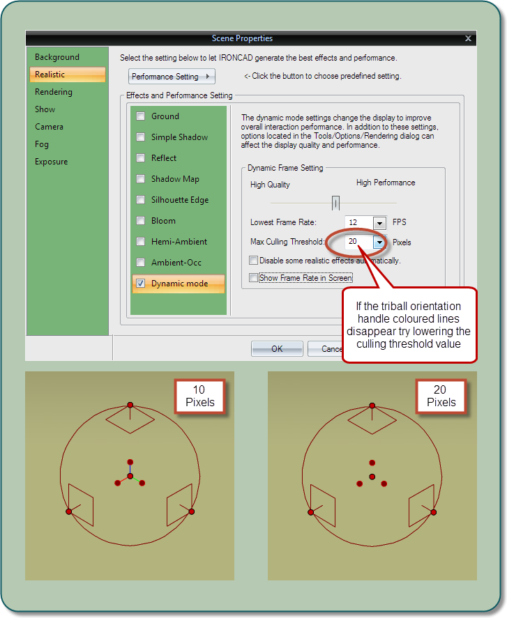
Thanks Kevin, I think I have found the fix. I have been playing around with the screen properties and I have found that the problem seems to be that the realistic rendering max culling threshold value was too high. I have attached an image for others to follow if they have the same problem. You may need to zoom in and out to activate the new setting.
-
Thank you for your replies. I thought that it might be difficult to reproduce because it is so hit and miss, but because I have been able to reproduce it, I assume it will reappear again at certain times. When I installed 2014, I updated my computer which included the latest updates for Windows 7 Professional (64 bit). Also, the graphics cards I am using are a Nvidia Quadro FX580 and an AMD Firepro V5900 which were updated at the same time. I have been able to reproduce this problem in both DirectX and OpenGL, but I have decided to stick with DirectX. Although this might not be a frequent problem (early days using v2014), I thought I would raise it to see if others report the same experience. Thank you.
-
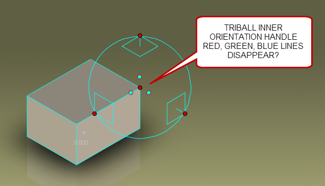
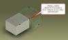
I have installed and have been enjoying the benefits of the new version 2014 but I have started to notice that the triball coloured legs of the inner orientation handles disappear at random. To get these legs to reappear, I have to exit the scene file and reload. Normally this works fine, but I have needed to do this a couple of times to get them back fully. I had no issues like this with the previous version, and I have seen this happen on both my home and work machine. I have attached an image of a screen shot together with the IronCad file that I saved after this condition had appeared. As I have already said, this is a random happening, so loading this file the legs will probably reappear. Has anyone else experienced this please? TriBall_Trouble_.ics
-
Thank you - that's sorted it.
-
I am using IronCad 2013 pu1. I have noticed a marker has been added before the part name in the browser tree. Can someone tell me what this indicates please? See attached image.

-
Thanks for your replies. Perhaps I should not have used the word project. I was referring to the dotted lines that extend from the smart cursor, the ones that disappear if you hold the shift key down. (As explained in the help section when searching smart cursor).
-
The import options in v2013 pu1 include options to repair and simplify the imported body. Whilst investigating these two options, I have not found that they make any difference to the models I import. I am surprised that when enabling the repair body option, which I assume is similar to the heal option in other CAD software, that the import time does not seem to increase whilst extra processing should be taking place. When I am importing some 3D models of round pipes, I was hoping that the simplify option would have converted the pipe diameter to true circles. I have increased the tolerance to try and force this, with no effect. Unfortunately I cannot post the model of the pipe because it is from a customer, but I am just wondering if anyone has got a model that they could post, which when importing the model with the features on shows a different result to when they were off. Any advice appreciated. Thank you.
-
I am using Ironcad 2013 vPU1 (64bit). Whilst in the 2D sketch mode, with the smart cursor enabled using v2012, I used to be able to hover over an entity which I wanted to project, and it was marked with a yellow cross. This helped reduce the amount of projected lines on the screen. (As mentioned in the help section for the smart cursor). However, in this version, it does not seem to work. Has anyone else found this please and if so, is there a method of enabling it?
-
I am not sure if this is a known issue, in V2013 PU1. I have assigned some Hotkeys in the 2D sketch area such as L=Line and C=Circle. These keys activate the command as expected, but when deactivating the command, the property input coordinate box is active and causes the Hotkey to enter text into it, instead of deactivating the command. This also effects using the single S key when using the floaty toolbox in this area as well. I assume other people are experiencing this. Thank you.
-
Thank you for your replies. I have watched Kevins video, and I have attached some images where the sketch plane is not parallel to the 3D object. When viewing this from an isometric angle, you can see which points are being projected to the sketch plane. I still feel that I only get positive projections from end points as indicated and the centre points do not seem to project the same. Perhaps there is nothing wrong with this feature as long as the user is aware of its limitations. A possible enhancement request might be to include more snapable points. Thanks again. Karen


-
I was reading an old document for What's New in version 10, and I found this feature being introduced to aid working in the 2D sketch environment:- Reference Snapping to 3D - During creation and modification of 2D elements, users can now reference 3D geometry without the need to project the geometry to the 2D Sketch. Holding the cursor over a 3D element for a brief second will place a reference indicator to the 3D element on the sketch. This indicator will use the SmartSnap highlighting behavior to allow the user to refer to the 3D reference element which reduces the time spent projecting construction geometry onto the sketch. Whilst trying to use this feature, I have noticed that whilst hovering over a 3D element, its edge reference is projected onto the sketch, but the only snapable parts are the end points on this element. Could someone please tell me if this is the intended use of this feature? Is there a way of snapping to other element features, such as line, midpoint or a centre point?
-
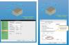
Thanks for your reply. I have investigated further and I seem to have found the source of the problem. If I enter the density value in the parts, property, material dialogue box and press OK, then it works fine. However, I have been editing the density value in the scene browser property tab, which I have docked on the side of my screen and shows the density value of a part when selected. This does not seem to update the density value in the analysis tool box. Now that I know that, unless it is different in the new release, I will just treat this as a read only box, and use the materials page in the part properties dialogue box. Does this make sense, and if so, does this happen on your version? Thanks again.
-
I am using V2013 PU1, and I am confused when using the tools analysis command whilst checking the mass value of parts and assemblies. I have now discovered that it is better to use the part or assembly property dialogue box, materials tab, for this value as I need to calculate the mass of assemblies with parts which have different material densities. The tools analysis seems to compute a different mass value. Have I misunderstood the use of this analysis tool, or should it compute the same value as shown in the parts/assembly property materials box? Please see attached image
-
Hi Tom A common example of this tipping analysis used in schools is a London Bus, where you assume the structure is rigid but pivots at an assumed point. The critical point for tipping is when the centre of gravity of the structure passes vertically over the assumed pivot point. Use this information at your own risk as I am no expert! But see the following link: http://www.antonine-education.co.uk/Pages/...Mechanics_4.htm Karen
-
Thanks for your replies. I have since found out that it does work fine on my work computer (Windows 7 Professional). However, it is my home computer that I have the problem on which has Vista operating system (I know it is not supported, but up to now it has worked fine). FYI, I have had some success with my home machine by altering the text height when the problem occurs, as long as the height isn't fixed with the font size. I didn't know if this might be something that the text height bug might be influencing. I have attached a video clip to show how I have managed to extrude the text without breaking it up into curves on my home machine. Thanks again. 2d_Text_Ext.mp4
-
In the Whats New in Ironcad 2013, I followed the video clip for the 2D Text in Sketch feature, and found that the text would not extrude as shown. I did find that if the text was converted to curves, using the break up command (right mouse button menu), it did then extrude, but you lose the ability to edit the text. Is this a bug or intended? Also, the text height value does not seem to correspond to the overall height of the text characters, for example, a capital "I" is not 10mm high when 10 is entered when using metric units. Has anyone else found any issues when using this new feature please?
-
When placing a 2D sketch within the scene, I cannot seem to activate the Quick Access pop up floating options box (See attached image) when pressing the "S" key. This item was introduced in Ironcad 2012 (Whats New). Can anyone help me find this Quick Access pop up toolbox please. I am using Ironcad 2013.

-
Can't find these features in Ironcad 2013
Karen Bond replied to Karen Bond's topic in General Discussion
Thanks Kevin. I found the scene browser filter. It seems like the main problem with the new curve selection option was that it uses the "A" key which had been previously assigned to "show all planes". Best wishes Karen -
Can someone please advise how to find the Scene Browser Filter Display Modes and the Advanced Curve Selection Tools, shown as two new features in the Ironcad 2013 "What's new". See attached images. Thank you.


-
Thanks for your help Cary, I can see the difference now. It seems quite obvious when looking at the direction of the green and red arrows. Thanks again.