Karen Bond
-
Posts
57 -
Joined
-
Last visited
Content Type
Profiles
Forums
Blogs
Downloads
Articles
Gallery
Everything posted by Karen Bond
-
Graphics Performance IC 2017 v IC 2016
Karen Bond replied to Karen Bond's topic in General Discussion
Thank you for investigating this issue. I have read your comments and have disabled all the realistic options and I can see that it does produce a faster fps than IC 2016. Therefore, I understand now that it is up to the user to set the options correctly for the amount of detail in the scene, to get the best quality/performance. Thanks again. -
Graphics Performance IC 2017 v IC 2016
Karen Bond replied to Karen Bond's topic in General Discussion
I have created two new files, one in IC 2016 and one in IC 2017. IC 2016 with simple shadow enabled showed an fps around 30 when showing both blank and holed face. IC 2017 with simple shadow enabled showed an fps around 25 when showing blank faces and when the holed face was visible, the fps dropped to about 6. On switching the simple shadow off, this improved to an fps of 25 on blank and holed faces. All these fps values were given when all blocks were visible. I have also deleted the xml files and reloaded the defaults with no change. I have already tried most options including the ones you describe, without any improvement. As a work around, I can switch off the simple shadow when the scene gets busy and use the reflection effect instead, without any performance loss. As for my second question, is there a way of switching off the additional text on the fps display? Thanks for your support. SIMPLE_SHADOW_2016.ics SIMPLE_SHADOW_2017.ics -
I have been using the latest Ironcad 2017 PU1 and I have updated my graphics card driver. I now notice that when I open a scene with a lot of parts/assemblies in (say 300 parts), I find that the graphics performance (frame rate) slows down as I rotate the scene when all the objects are within view. Zooming in so that some of the objects are not in view speeds up the frame rate. I had no lack of graphics performance in IC 2016 with this scene, and I have set up IC 2017 with all the same settings as I had in IC 2016. However, I have noticed that what is causing the problem is having the simple shadow option enabled in the screen properties. Disabling this feature brings it back to the same performance as in IC 2016. Has there been any enhancement in this feature to cause it to have this effect? Also, when I was using IC 2016, I used to have the frame rate constantly on show in the top left corner of the screen. In IC 2017, I notice that you have added a line of text to this frame rate number. Is it possible to switch off this additional text without removing the whole frame rate display, as I find it quite distracting? Thanks.

-
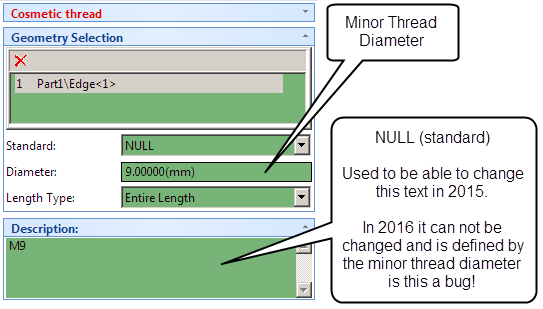
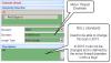
I can't seem to edit the cosmetic thread description, has something changed? Please see attached image. Thanks Karen
-
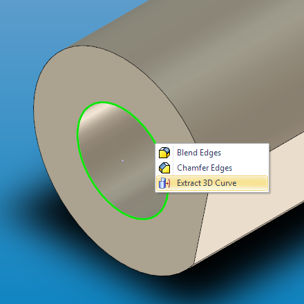
Whilst using IC2016 SP4, I have found an issue with extracting a 3D curve from a full round edge in the attached part. The other edges of the part extract OK, but the edge in question creates a part but when opening this part, the 3D curve does not show up properly. Any ideas what is causing this? Thanks Part1.ics

-
Thank you for replying.
-
I am still using 2015 because I am waiting for the ICD text bugs to be fixed. After installing 2016 SP2, I noticed that there are still some text issues. Are you still working on fixing these issues, or is it a closed subject? My issues are (which have already been documented by others and recorded as bugs): 1) In 2015, when you created a text with leader, the text box would automatically lengthen to suit the text length. In 2016, it is squashed up and needs an extra step to stretch the box. 2) In 2016, when selecting text to edit within the text box, the text format changes to centre for any new typed text. Although in SP2 it reverts back to the original text justification, the new typed text is left centred unless an extra step of re-formatting is done. 3) In 2016 when exporting to pdf file, any text with leader that has right format becomes misaligned. (Although cute pdf could be used via print, it does not give the same quality output as ICD export.) Can you advise me please?
-
Thank you for replying.
-
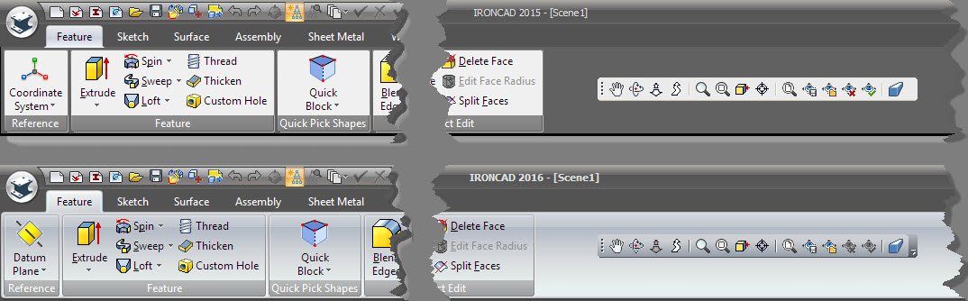
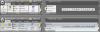
I have recently installed Ironcad 2016, and have noticed that the ribbon bar black style colours have changed slightly from the previous 2015 version. In particular, the white background has been replaced with a grey effect which reduces the clarity. Although this is not a major problem, I was just wondering if there was any way to change the colours back to the previous black style? Please see attached image.
-
Moving the Triball off the Anchor Position
Karen Bond replied to Karen Bond's topic in General Discussion
Thanks for checking. I wonder if it could be logged as an ER please? Thank you. -
Moving the Triball off the Anchor Position
Karen Bond replied to Karen Bond's topic in General Discussion
Thank you for your reply. In Ironcad v2015, when you turn the Triball on (F10), the anchor pin is hidden whether the Triball is on or off the anchor position. I am not sure, but I think in previous releases the anchor pin still remained visible with the Triball on, which would give some indication of the Triball position in relation to the anchor. -
When relocating the Triball using the spacebar option, Ironcad v2015 now remembers the new position and orientation of the Triball. I sometimes forget that the Triball has been moved off the default anchor position and wonder if there is any visual indication to show that this has happened. If not, it would be helpful if the Triball could have a different colour assigned to it, if it is not in the default position. Any thoughts please?
-
Cosmetic thread image not showing on surface
Karen Bond replied to Karen Bond's topic in General Discussion
I have reinstalled Ironcad and it is working fine now, thank you. -
IC2015 PU1 Win7 Pro (64-Bit) Since updating to PU1 I have noticed that dragging a custom hole from the tools catalog and specifying a threaded hole will not automatically show the cosmetic thread image as it did before. This also has effected the nuts and bolts thread display in the fasteners catalog. I assume it is repeatable be others and would like to know if it can be easily fixed? Thanks Karen
-
Thanks for the reply Kevin. Does that mean that the tightness relates to how much processing occurs when using this mode? So, do you start with the standard option and if you want it tighter choose rigid, or looser choose relaxation? Not sure what the localised option would give? Have I got the right idea? Thank you.
-
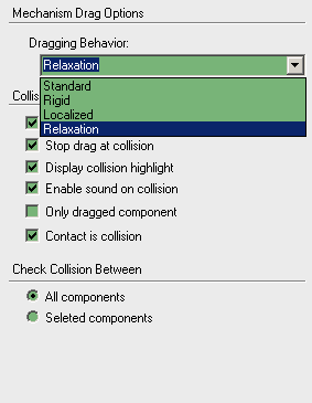
I have noticed that in the mechanism mode there are four different dragging behaviours listed. One of them is new in v2015. Could someone please explain when to use these different behaviours, as I normally just use the standard behaviour, but would like to know the difference between the others. They doesn't seem to be mentioned in the help documentation. Thanks.

-
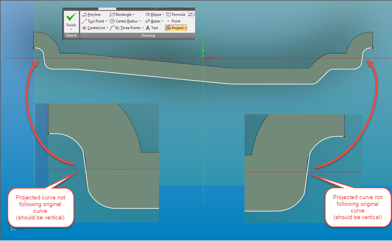
2D Projected Curve from Model Edge Display
Karen Bond replied to Karen Bond's topic in General Discussion
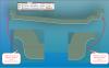
Thanks for your replies. BTW, I think something similar to this is happening when you use the extract 3D curve on this same model edge. The display shows a faceted outline which, in places, runs off the edge profile. -
Attached is an image showing the result of projecting a surface edge into the 2D sketch environment using the project command. (IC2015) I have noticed that a couple of edges do not display in line with the original surface outline as shown. I have also attached the surface model file. Does anyone know if this is just a display limitation, or is it producing an error? The shape was originally imported from Rhino. Thank you for any help. Scene1.ics
-
That's great, thanks.
-
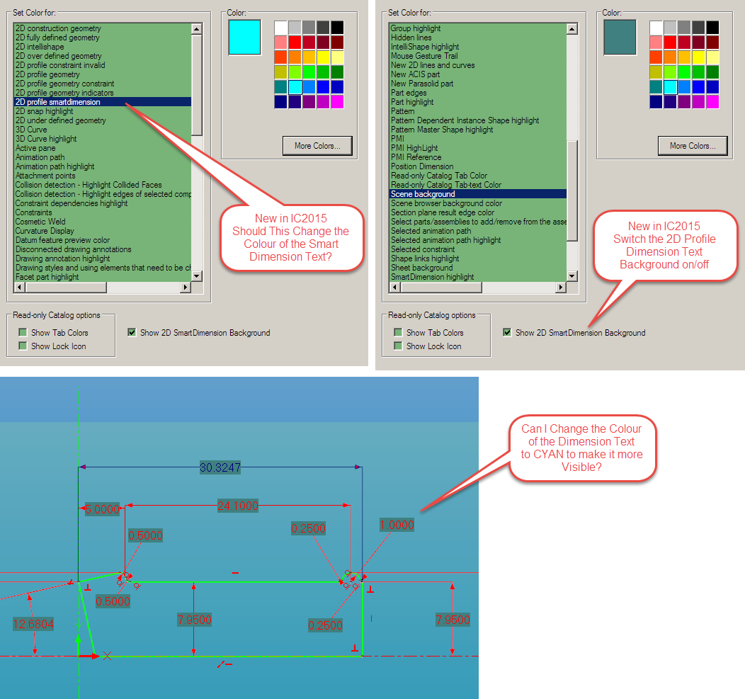
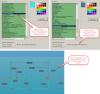
I have started using Ironcad 2015, and I have noticed a change when using the 2D profile sketch dimensions. When I used Ironcad 2014, I had the 2D profile dimension text set to cyan, because this made the text very visible against the dark background. I am now trying to change the text colour in 2015. I notice that in the options, under colour, there is a new item listed named 2D profile smartdimension, but changing the colour for this option doesn't seem to have any effect. What does this option effect please? I know as an alternative, I can change the text box colour background if necessary. Please see attached image.
-
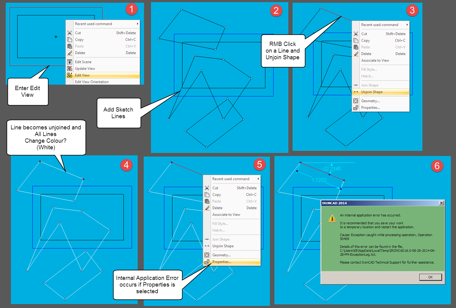
Using Ironcad 2014 SP2 64bit. Win 7 Pro. After creating a view in an ICD drawing, I then used the Edit View command to manually sketch some more lines into the view. Everything worked fine until I selected a line and used the Unjoin command. Then, all the drawn lines went white, and I had to exit the sketch and all the lines were lost. I use a blue colour for my drawing sheet background, otherwise I assume these lines would have been made invisible. Trying to change the white line properties caused an internal application error. However, when sketching directly on the sheet background, and not in a view, the command works OK. Not sure if this can be repeated by others, or whether it is a new or known issue. The attached image shows the steps I took.
-
3D Curve Polyline Selection Not Highlighting
Karen Bond replied to Karen Bond's topic in General Discussion
Thanks for the video. I have now got it working, but I had to switch off two display options, show co-ordinate system and show position dimensions. I assume you will find what I had originally if you switch both of these options on? Thanks again. -
Ironcad 2014 SP2 (Windows 7 Prof 64-bit) When I draw a 3D curve using the Polyline tool with 4 or less segments and LMB click to select any line segment, it highlights yellow. If I redraw a completely new 3D Polyline with 5 or more line segments (or add more segments to a 4 segment Polyline), then LMB click to select any line segment, it selects but does not highlight yellow. Is this a known issue please?
-
Thank you for your reply. Now that I know that it is a bug, I will have to draw my own leader line when the standard is not suitable. The second point was that the leader options tab, which appears on the normal property dialogue box (right mouse click on leader), does not appear in the styles dialogue box when creating a new text with leader style. But now I know that this feature doesn't work, it is not an issue. Thank you.
-
Just another small query. I have noticed that if you reposition the text box leader with the option given in the properties dialogue box (left, right, down and up), it will revert back to its default position if the text box is dragged. Is this intended, or is there a way to stop it resetting? I have also noticed that this option to reposition the leader does not appear when constructing a style for the text with leader. Is this also correct please? Thank you.