
Jonas@Solidmakarna
-
Posts
2,287 -
Joined
-
Last visited
Content Type
Profiles
Forums
Blogs
Downloads
Articles
Gallery
Everything posted by Jonas@Solidmakarna
-
Hi Joseph, I've been running IC v2015 on Win 10 Tech Preview running in a VirtualBox environment without any issues. I guess it still has to be thoroughly tested by the developers, but I haven't seen any significant issues so far.
-
Hi, First, the option "Do not process linked files" means that only the main assembly file will be saved while all externally linked files will be kept as is - but still linked. The yet to come(?) option "save-and-brake" would be really useful for many users. Second, you have a somewhat hidden tool under the File menu -> Find References in which you can see all the externally linked files and brake them one by one with a button. There's no Brake All button, but it would be very useful if it was added as well! Also notice that if you have installed IronPRO XT there's a tool in the ...Tools catalog - External Links Manager, which brakes, replaces, opens and saves external links. It can brake all, brake only selected or brake selected including all sub links in assemblies. A very powerful and useful tool that I really recommend!
-
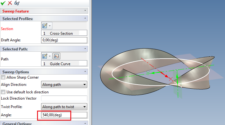
Hi Tom, I got the question how the Triball would look if it was modeled in IRONCAD from a participant at a training a couple of days ago, so I made a quick model just to see what happened. Though it is made in the PU1 beta, so it won't open in IC until PU1 is released and is neither small enough or really "printable" Triball.ics

-
Hi Eric, Try lowering the screen resolution, to say 1680x1050, just to see what happens. Make sure that IC is closed before you make the change. From my experience those Quadro Kxx00 cards are working really great and we have several users that recently upgraded from older Quadro cards with fantastic results. I know at least three that bought the new Quadro K2200 and it is running like a charm. How many parts do you have in the scene?
-
Hi Nick, The Scene background setting controls the dimension background as well. I don't know how to change the color of those that are controlled by expressions.
-
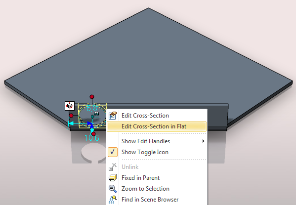
I would do like this and use the Edit in Flat option. See the attached file, saved in v2015. BentSteel_Corner.ics
-
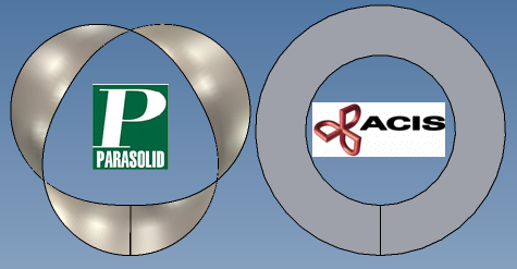
Keep to Parasolid

-
It was easy to change it as well, cool!
-
Sorry about that, "rm menu" has been used quite a lot here so you get kind of blind. I'm glad to hear that it's getting clearer.
-
Hi Harley, First, I can't see that there's a problem moving one or the other of the SheetMetal parts, the hole stays where it is. An Assembly Feature does not create a Part feature instantly. That is an extra option on the rm menu of the feature in the AF - bottom option "Create Part Feature". At that moment the AF will be emptied and the hole is copied to each part affected by the AF. To get a hole in the unfolded part you must have a part feature, so you must do this sooner or later. You can easily move parts and features in other parts (even features in parts below other sub assemblies) by holding down the keys ALT SHIFT when selecting. This way you can first select the nut, then hold down the ALT and SHIFT keys and keep on selecting the holes to the same selection. If you want to add extra parts, release the keys and press CTRL SHIFT instead, now adding parts to the selection. Then turn on the Triball and move/copy/link or whatever. Combined with somewhat transparent parts and display of hidden edges (CRTL K on selection) you can easily select features this way. I use it quite a lot myself! So, you can start off by dropping your AF group with the nut, then create part features at any time and still be able to move them together.
-
Differing results with closed corners
Jonas@Solidmakarna replied to HDEAR's topic in General Discussion
I usually never use the In our Out Bend shapes, the issue mentioned above is one reason. Another reason is that the size of the part should be set after you've made the principal "shape" of the part. So just drag out the features needed, then go through the dimensions, it is much faster and easier. Though probably not how people are used to think and that is why this question usually comes up. Also make sure that you have the Options, SheetMetal setting "Auto-Constrain bends" active, so that everything follows when you change the dimensions. When working with SheetMetal in IRONCAD you should use the Shape (profile) handles. They are really great and work in all situations everywhere. You can have a look at this video (from 40s), I hope it helps eventhough the built in video comments are in Swedish - -
Expansion of Assemblies in Drawings
Jonas@Solidmakarna replied to Eric Foy's topic in General Discussion
Hi Eric, It is important that you change the Assembly Expansion in BOM setting, not just the "Treat as Part" and "Expand", but also if the setting should be set for all linked instances or just this one instance. In the Top Assembly, the settings should be; Treat as Part Only this assembly In the Sub Assembly, in the external file, the settings should be; Expand Only this assembly These settings are not yet shown in the Property Browser for the assembly, only under the rm menu Assembly Properties. This makes it quite easy to miss, specially for newer users that hardly knows about the Property window for parts and assemblies. But I guess you still rm click to edit as you've always done? At least I'm still quite old fashioned there... This way you will have a BOM showing the sub assy in only one row in the BOM for the top assy, but all parts/assy shown in the BOM for the sub assy.
-
TraceParts is a good site for downloading 3D models of products from a lot of companies and use in your IRONCAD projects, instead of making the models yourself. If you're not a member and have a login, then you should think about creating one within the next 3-4-5 weeks and you might win a cool price. http://www.tenlinks.com/news/traceparts-en...gistered-users/ Good luck! Another good site is Cadenas, where you can download files in the ICS 3D format and insert as a link to your assembly file, which is a good way of keeping up the performance in large assemblies. http://ironcad.partcommunity.com/portal/portal/ironcad and in Sweden we have a very good site called http://www.solidcomponents.com/ which is also working fine for many other European countries and languages.
-
Nice! Thanks Tom!
-
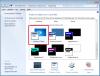
Hi Troy, It is because your scene browser is "floating" and not docked to the side. Have a look at this video. SB_Floating.avi (Camtasia recording, if needed download CamPlay here: http://goo.gl/kZ6Pua )
-
H Slots and H Cylinders on unfolds not showing
Jonas@Solidmakarna replied to HDEAR's topic in General Discussion
For a rolled sheet metal - tube Drop a Stock from the Sheetmetal catalog. Drop a Bend on an edge. Delete the first Stock shape in the part Edit the Bend radius and length, say 359 degrees for a tube looking part that can be unfolded. Adding a hole: Drop a Custom Profile (the very last icon at the bottom which is creating a hole). - when dropped, try to "aim" for one of the "corners" of the tube, where you can see the 359 degree part edge running along the length of the part. Then you will get two smart dimensions which makes it easier to place the hole at the correct place. The hole position is edited like it the sheet metal part was unfolded. I you only get one smart dimension, try placing a new hole. Delete the first one. Hope this helps. -
Re-orienting unfolded sheet metal doesn't work, since it has a set orientation in space. It will move back to where it was. That's why F7 and From scene is so fast and easy to use.
-
You mentioned "struggling with F7", but I think the easiest thing to do is to use the "Look at" tool (F7) in the Scene, then use the option "From Scene" when you create the view. That has been working very well in cases like this for years.
-
How to identify external linked files
Jonas@Solidmakarna replied to bbraho's topic in General Discussion
If you're using IronPRO XT you also have the tool External Link Manager, which is really great. - Break all links (or selected only) - Save with a new name and/or in a new folder - Replace an external file with another file etc... -
animation a belt
Jonas@Solidmakarna replied to tlehnhaeuser's topic in Realistic Rendering and Animation
It was a very cool animation! Tom, if you change the color of one chain link part you'll see how the animation is made. If you haven't already found that out -
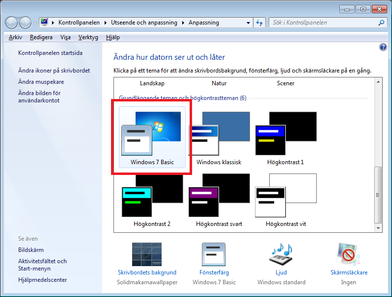
Hi all, We've noticed that changing the Windows 7 theme to "basic" has quite a big impact on performance. First of all you should turn off the Windows Transparency, it is a big performance stealer! But we've found that using the Windows 7 Basic theme also improves the speed of right click menues, and other things in the program that "should" be working fine even though you might be working with large assemblies.
-
Great work and a well done tutorial Joseph!
-
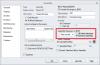
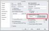
Hi Karen, Snapping to line end and mid points seems to be working fine, both when drawing a new line/circle and when editing a knee point or a curve dimension point of a selected line. Though center points of holes/circles shows a snap point (if you have the hole surface behind the point, you need to rotate the camera some to do this) but doesn't seem to really find it. At least not on my machine. Also make sure you have this setting applied:

-
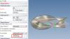
I replaced the Extrude Draft setting with a Draft Feature instead. It will work, but only using the ACIS kernel before exporting. ICExportTrouble_JB.ics
-
It might be the combination of the Extrude Draft angle and the Shell. If I change the draft angle from 3 to 0 degrees and change the kernel to ACIS the STEP exp/imp works fine.