
Jonas@Solidmakarna
-
Posts
2,289 -
Joined
-
Last visited
Content Type
Profiles
Forums
Blogs
Downloads
Articles
Gallery
Everything posted by Jonas@Solidmakarna
-
ISV Application Certified or new Radeon Pro drvrs
Jonas@Solidmakarna replied to jolizon590016's topic in General Discussion
I installed the latest drivers from here yesterday; http://support.amd.com/en-us/kb-articles/p...cs-drivers.aspx It was on an HP ZBook 15 G3 with both an Intel 520 and an AMD W4190M, where the AMD card was "dead" and the HP support couldn't help us getting it started. After the installation of the latest drivers we were able to dedicate the AMD card to IC and get the full potential out of the system. They have a certain option for that when you right click on Windows Desktop. Before that IC (and Windows) was slow and had some strange effects. -
Unwanted results of update to BOM in icd
Jonas@Solidmakarna replied to HDEAR's topic in General Discussion
Hi Mike, Regarding the blank lines in the BOM, I agree that it would be helpful with a visual help to find out which blank row that belongs to a certain object. A mouse over on rows maybe could light up the part, similar to how the item bubble does. I usually say that when you create the BOM, you should already know what comes up there. To do that we use the PROActiveManager BOM from IC Mechanical/IronPRO XT. It has many useful BOM tools and you can create many different types of lists from the same scene, just by a few settings and BOM templates in 3D. Find out more about it here, where Part 1 shows handling of properties and Part 2 manages the BOM tools: -
Regarding the Options settings, you can read more about some recommended settings and maybe some explanations, here (google translate...): https://translate.google.com/translate?sl=s...t-text=&act=url The only setting that has a big impact and which isn't default is the "wait to regenerate..." under the Parts settings.
-
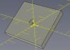
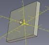
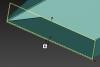
If I understand the problem correct, the plate is not oriented planar to the "paper" of the drawing? There are usually two orientation issues to deal with; 1) rotated around one axis (X or Y, not the Z-axis): Use F7 (Look At) and select a front face of the part in 3D, then use the From Scene button when creating the drawing views. 2) rotated around more than one axis: If you're ok with having the part rotated around itself in the "screen axis" (or Z-axis), but being flat on the drawing, then the above solution works fine here as well. Otherwise you'll probably have to create a configuration and reorient the part parallel to the coordinate system in it (not affecting the original orientation) and then make the drawing view from that new configuration. In the coming v2018 there will be a new option to control the Front view direction directly in 3D on the part itself. This will make this a lot easier!
-
I agree that this is hard to grasp if no one has showed you how it works. There should be some visual information added that helps. A change that came a few years ago (first in v2012 and then improved in updates) was the way the Triball "reads" the direction of edges and faces. When you've learned it you don't need to right click the inner handles for options, just left-drag the handles to the edge/face. Fast and easy! You can also use the Shift key to snap to end and mid/center points, when dragging the Triball center handle. Now when you select the edge to be parallel to, the edge has two directions - from the mid point and out. Up/Down or Left/Right depends on which half you choose. Same goes with Parallel to Axis option when choosing the cylindrical face of the hole/shaft. The reason why it feels like it always goes in the wrong direction is that the nearest edge most often points in the opposite direction. You can choose the opposite handle.
-
Yes! I am always on a beta
-
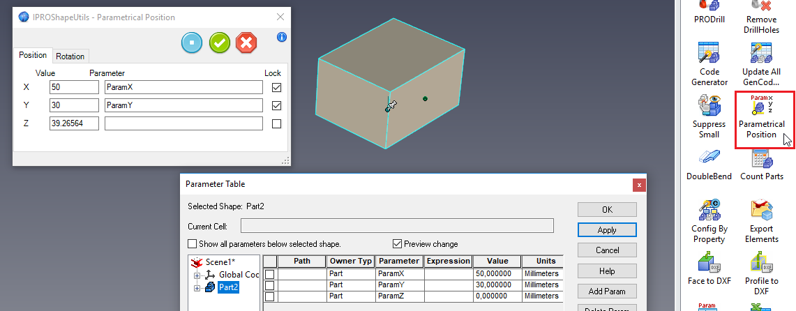
Hi Tom, With the IC Mech Tools Parametrical Position tool you can achieve this. First, create the parameter on the part, then drop the tool and apply the parameter to the coordinate.
-
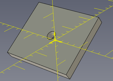
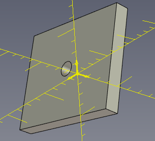
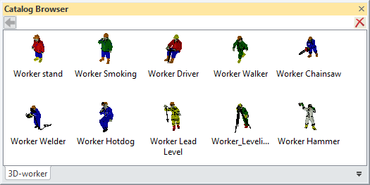
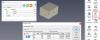
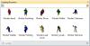
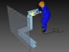
Here's an Expanded Metal part with a texture on which will stay put on the part when the dimension of the Block feature is changed. The part is transparent due to the texture on the front and back faces. This makes it more easy to place an expanded metal part in the scene, then to actually model it The Part Name in the Scene Browser will update with the dimension and thickness (only if you have IronPRO XT or IronCAD Mechanical, created with the Code Generator tool). Expanded_metal.ics (the welder and steel beams are not included) Bonus! Here's a catalog with different 3D Workers: 3D_worker.icc
-
I think the only way to move a part and at the same time extend another is using the Stretch tool or using an assembly level handle, but that would involve adding one or more locked dimensions to the objects in the assembly. AssemblyHandles.ics
-
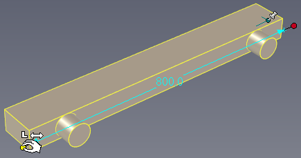
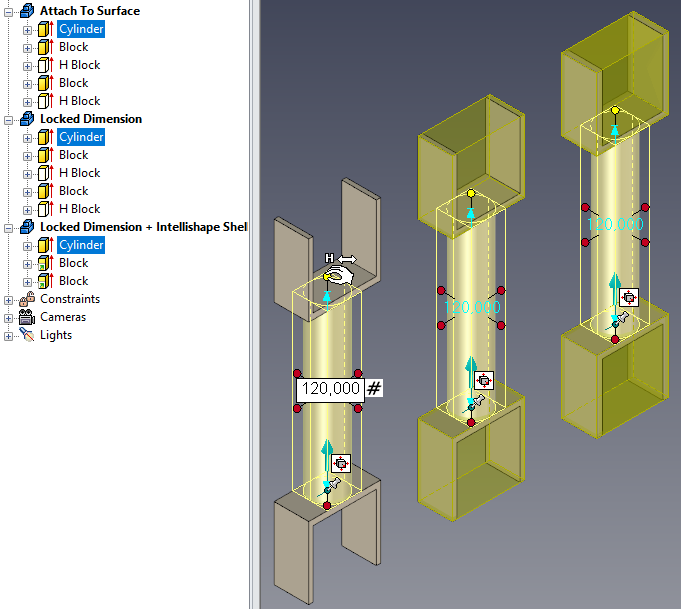
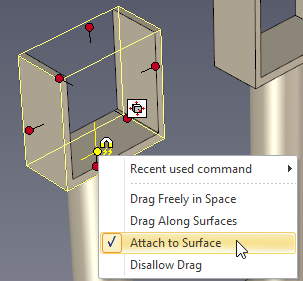
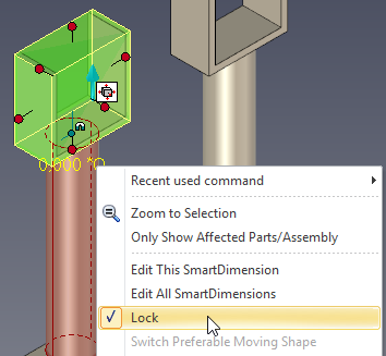
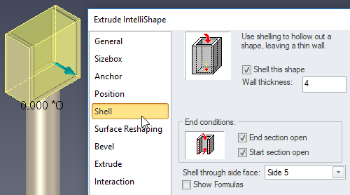
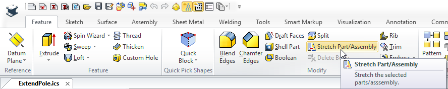
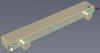
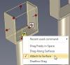
Here are a few examples on ways to do it (which doesn't involve using the Stretch Tool, which might be the best option for unplanned changes). Also remember that you can hold down the [Ctrl] key to select more than one Sizebox handle. ExtendPole.ics 1) Using "Attach to Surface" on the Anchor Point. This is quite easy and stable over time, but depending on the changes made the anchor point might change from "Attach to Surface" to using "Drag along Surface" instead and the shape won't follow. 2) Using a Smart Dimension as a constraint between the Block and the Cylinder. This is sometimes useful but you need to do the extra clicks to add the Smart Dimension, edit it and lock it. 3) Same as 2) but the Block features are using a "built in" Shell function in the Intellishape properties instead of negative H Blocks, to make the Part structure more compact. Btw, the Stretch Tool is found under the Feature ribbon:


-
And I would probably make the holes (in your original part) as stand alone features (Custom Profile) instead of drawing them in the sketch of the Stock (main feature), since it makes it easier to move them afterwards. Either by using the Triball, the Position Dimensions or using the Stretch tool.
-
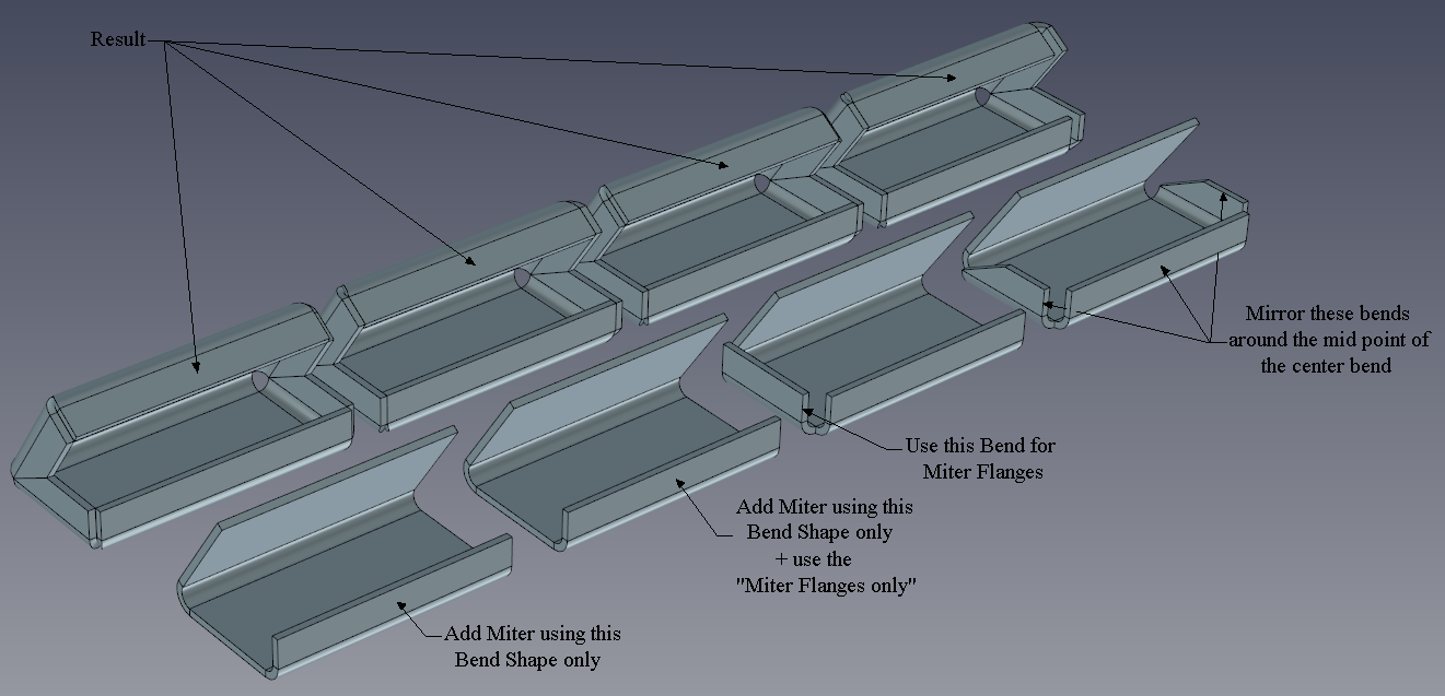
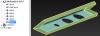
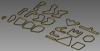
Here are 4 ways of modeling the same part, depending on how you use the Miter Flange and Mirror features on the bends. As you can see the "Closed Corner" only works with certain corners due to the effect of the Miter Flanges. MiterBend_Difference.ics
-
No, that's true! I didn't use Out Bends and I never do that in general either. Everything works much better when you don't use In/out Bends and you never really have to use them either. This comes down to how you think when you're working with the Sheet Metal parts and tools. With the new Associative Edges settings it might be easier to solve certain shapes and harder in other cases. You need to learn the pro's and con's of the settings. The bug report you made is still valid for Out Bends, but I just wanted to show that you might be able to do it anyway, in another way.
-
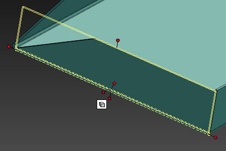
Is this part ok? SM_Part49_CF_957.6_Mirror.ics I found that if you add a bend, then use the Miter tool only to create the nice looking flange and remove the Miter again - the bend is still cut in the angle. Using the Mirror tool to copy the bends to the other side seems to be working fine.
-
It's because the Miter tool changes the settings of the "bend extension" (or leg) of the bend feature. It doesn't do any changes to the curves in the stock. A Bend with Stock is actually two features in one drop.
-
Forgot to upload the ics files! Flexshape_CamBelts.ics Shaft_CamBelt.ics
-
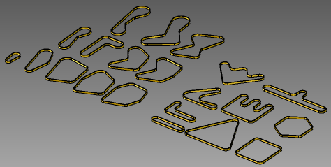
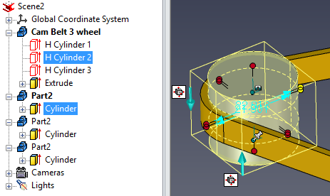
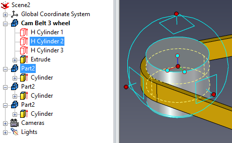
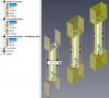
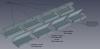
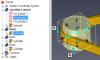
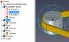
I've made some different belts using the Cam Belt part from the FlexShapes catalog as a base. It's really cool how easy you can work with the shape of the belt by selecting the (negative) shape in the history tree of the part and then move or edit the size! To move a shaft and at the same time update the belt shape in real time, first select the negative shape of the belt in the scene browser part tree, then hold down [CTRL] and [sHIFT] keys and select the shaft in the 3D scene (not in the tree). Then activate the Triball to move them both. To change the diameter of the Shaft and the belt at the same time, first select the negative shape of the belt in hte scene browser part tree, then hold down the [ALT] and [sHIFT] keys and select the shaft in the 3D Scene (not in the tree). Then use any of the diameter handles.
-
Tools Add-on Properties Custom Hole
Jonas@Solidmakarna replied to jolizon590016's topic in General Discussion
Joseph, I can assure you that you are far from the only one not noticing the drop down options on various icons! I'm not a big fan of those either, specially not when there are plenty of room for most tools to be shown under the ribbon tabs and in my opinion there could be more tabs added if it gets too crowded in one tab. -
Renaming a current 3D scene with associated icd
Jonas@Solidmakarna replied to jolizon590016's topic in General Discussion
Hi Joseph, If you have the ICD opened it will automatically be re-associated with the new name of the ICS file (you get a message about this). If you don't have the ICD open it will not re-associate to the new ICS file name. I think IC Mech has a batch tool in the Win Start menu to change which ICS file the ICD should be associated to. I'm a little rusty on that tool, so I'll have to get back to you later with some more info. -
Views not appearing on ICD from 3D
Jonas@Solidmakarna replied to HDEAR's topic in General Discussion
Hi Harley, Maybe the uninstallation tweaked some of your file associations. I don't recognize the issue and it shouldn't happen, but I've seen something similar happening on a computer a few years ago. I usually never recommend a complete re-installation, since I believe that most issues can be solved in easier ways. In this case, since you've removed IC as a last step, maybe you should repair or re-install v2017. It is actually quite fast nowadays. Only original files will be restored, so none of your added templates etc should disappear. But if you replace original files you should keep a backup of them. Merry Christmas! -
Great tip Tom! When you've done this a few times and feel "safe" you can even save a couple of clicks by copying to a 0 distance and press [delete] (or suppress) right after you've made the Triball copies and turned off the Triball.
-
2D Drawing options for grid in the scene
Jonas@Solidmakarna replied to jolizon590016's topic in General Discussion
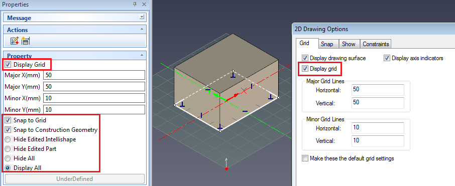
Ok, the grid resolution! It is a default setting in the scene (for a new extrude etc) and per already existing feature. In our metric scenes we've created a new extrude, changed the default resolution then cancelled so that no new part is created. There's actually a register setting for this, but I'm not sure it is used anymore. This is something that support needs to answer. For stuff that you drop from the catalog it is saved per item. So, there's no general setting that will update all already existing features. They have their own individual setting. Please correct me if I'm wrong. -
2D Drawing options for grid in the scene
Jonas@Solidmakarna replied to jolizon590016's topic in General Discussion
Hi Joseph, Which 2D Sketch grid options do you mean? For me the "Display Grid" for example is a global setting. If I turn it off on one extrude in one file and then move to another file, editing an extrude there - it will also be turned off. I can change and move to another scene and it will change when I get there. That goes for all settings found in the Property Browser (except the grid lines major/minor values).
-
Hi, This is something that a PDM system will take care of. Have a look at DesignDataManager for example. A part/assembly can be used in many other places (called "where used" or "used on" in PDM a system). So you may find more than one "parent". An assembly is built of parts and sub assemblies (called "requirements" or "consist of" in a PDM system). This is obviously also seen in the CAD system.
-
Hi! You could either change the system decimal to a point (dot) or change the values to higher than 0 using . as a decimal. Then Preview to update. This was reported a while ago and got Incident ID#: 107478