


Jonas@Solidmakarna
-
Posts
2,287 -
Joined
-
Last visited
Content Type
Profiles
Forums
Blogs
Downloads
Articles
Gallery
Posts posted by Jonas@Solidmakarna
-
-
Hi Will,
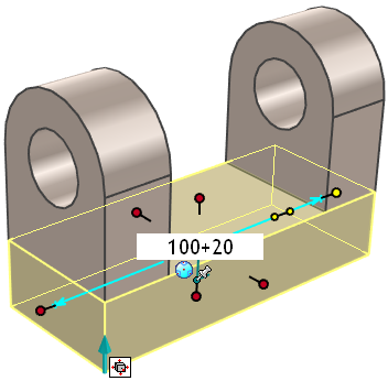
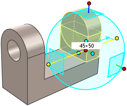
One of many new nice features in v2019 is the requested function to not having to switch to "formula mode" per session.
You just type your formula in the dimension input box!
-
Hi Will,
Welcome here!
This is what doesn't work? If so, it sounds really strange. It might be a graphical issue.
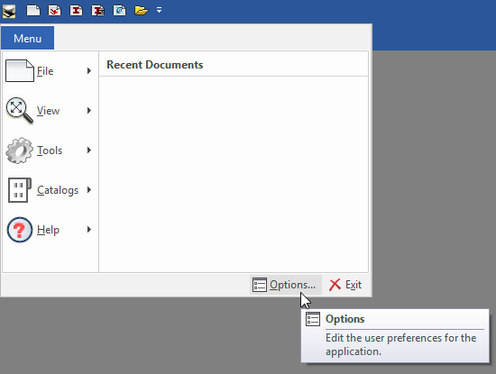
Close all open files go to the Options:
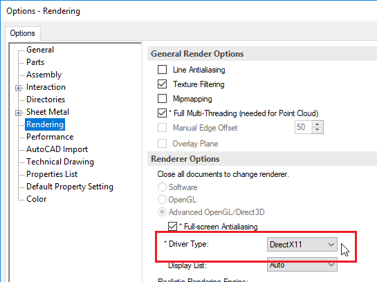
There, change to another Rendering Engine and open a scene and see what happens.
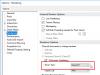
Close the scene before you change to another setting.
I guess you had v2018 on the same computer? Which graphics card do you have?
-
Really good!
The edges and handles looks like they should as well =)
-
Heard about this, but haven't tried it myself
-
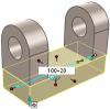
As long as the one who is using them (the advanced shapes beams) understand that the current dimension that he has set might not follow a standard that actually exists. They are only schematic shapes!
-
This is a very common problem when you start with IC, maybe the "most common"!
I usually recommend users to make a copy of the part (as many copies as "there should be parts") and then delete the features/Intellishapes within each part that doesn't belong to it.
In the IC Mech Utils catalog theres a tool named Split Intellishapes that does this as well. But I would recommend the slower and more obvious way of copy/delete.
-
You can also go to the "Edit feature options", change to "Add Material". Move the tri-ball to the desired location, and then go back to the "Edit Feature options" and change back to remove material. It may not be as quick, but I have used these steps for other things once I learned it was there.
RJ
That was a great tip RJ! In the IC Mech Utils catalog you have a tool named Solid/Hollow Toggle that you can drop in the background when you have selected the shape to switch. It makes it a bit faster

-
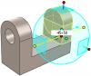
The corner that you see is only a visible (graphical display only) extent of the shapes "box". It doesn't really "exist" as a geometrical point, which is what the TriBall is looking for.
The easiest way is to move the H Block inside the positive geometry and place the TriBall on the geometrical "corner" that appears and then (move it back and then) forward to where you want to go!
-
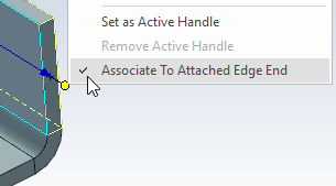
Yes, this is a new, probably unintentional, behavior because of the "associative to edge" function.

It is only possible to edit the shape using the Sizebox handle, but after you've done that (or if you deselect that option on the Sizebox handle) it should then be possible to use the Shape handle and its menu as well. Though that doesn't always seem to be working. This is known and should have been reported before as well.
-
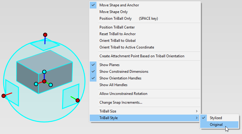
+1
Colors are always good! Clear and distinctive.
-
Remember that you can find and select SmartDimensions in the Scene Browser as well.
-
Hi Steve,
You can control the default transferring of Thread information and more under the Sheet Setup (right click in the background). Then remember to save the changes to your template file.
I agree that tables in the ICD should be easier to control and there are a number of enhancements placed for this since before, but I don't know the current status of them.
-
Hi Peter,
As you say, there are functions for this in the ic mech addon.
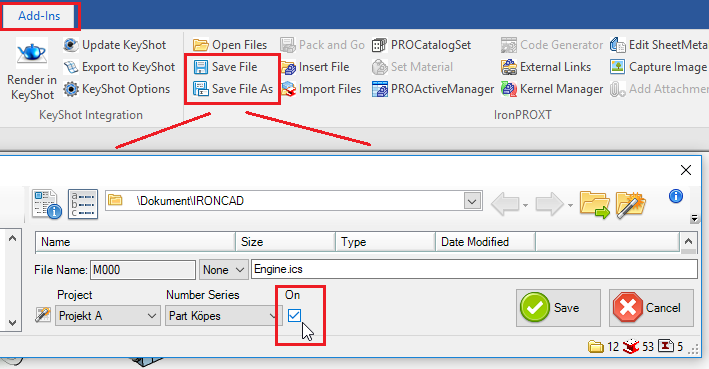
You can find an "alternative" save function in the IC Mech group under the Add-ins ribbon bar (hint: these tools will soon be found under their own ribbon bar
 ).
).When you use the save function the part numbering tool can be applied and it will add the number to both the file name AND the part number of the part/assembly that you are saving.
You have a video with swedish voice (still possible to follow I hope!) here:
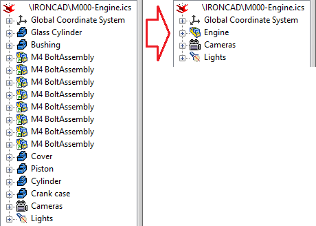
Btw, it is always important to assemble everything in a scene into a single assembly in the scene browser, instead of having multiple parts and assembles scattered. This will make the future use of the file easier since you have control of the assembly properties etc. when it is being reused with the Insert Part/Assembly function.
-
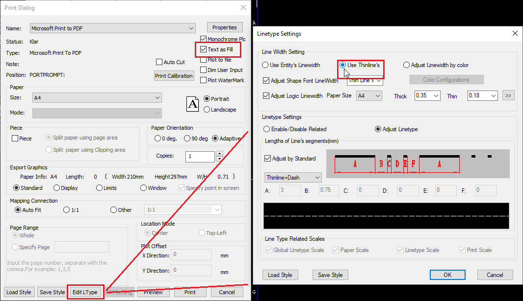
Try how these print settings are working out for you:

-
Hello Ian!
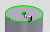
Make sure to select the hole and not the profile, before you create the Smart Dimension. The selected object is always the "owner" of the dimension when you create it.
-
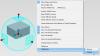
Starting with version 2018, the Quick Command (S Key) menu pops up automatically with every click.

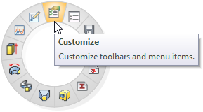
If you prefer to revert back to the menu only popping up when you press the S Key, invoke the menu and click the top most button labeled Customize.

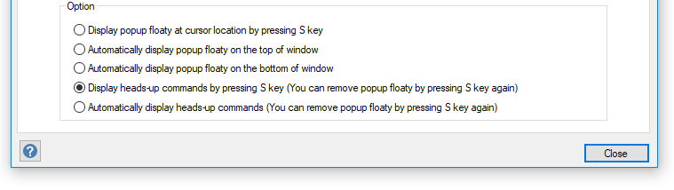
Then you can select the option second from the bottom in the dialog that sets the menu to only popup when the S Key is pressed.
-
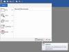
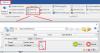
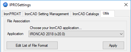
With IronCAD Mechanical you have a tool called IPRO Settings (found in the Windows Start menu) in which you can set the ICS file to open directly in the existing process, which, by some reason, doesn't seem to be the default behavior.

Just make sure that the list of formats don't include file formats that you don't want to connect to the open function, with the button Edit List of File Format.
-
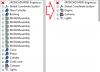
When you want linked parts or assemblies to have different names (maybe right vs. left) you find that setting under the Part Properties, below the User Name. You choose either This part only or All linked instances.
The reason why this can happen in an assembly is the option that Kevin showed above. When you open an assembly there might be linked instances in different external links which have changed individually and then a question appears when a higher level assembly is opened - asking you if you want to keep all linked names or if they should be set individually. If they are split up individually you must manually change the Part Property setting back to being linked again. I think the message is a bit unclear on this, it has way too much text. I would prefer an image instead.
-
Support should have a look at this. I would say that the PDF export from the ICD is working very well in general nowadays. Maybe you should try changing from Draft Mode to Precise Mode on the view properties and see what happens.
Here are a couple of PDF creators that I have used before (Win 10 now finally has a built in PDF printer and it actually works!
 )
)CutePDF, small and reliable.
http://www.cutepdf.com/Products/CutePDF/writer.asp
Bulllzip, this one can be modified for batch print mode, without any questions during export = a fast way to create PDF files of all the ICD files in your project.
-
If you suddenly find that your spacemouse has stopped working, it might be because of a bug in the current (10.5.4) 3dconnexion driver.
We've seen a couple of cases and the drivers are still not updated to solve this issue.
Read more here: 3DxWare not loading
This is a bug. Sorry about that. It will occur if you don't use the device for 7 days in a row.It has been fixed for the next release which we are testing now.
I believe all you have to delete is the file: %LOCALAPPDATA%/3Dconnexion/3DxWare/3DxServiceState.xml.
-
I think these look really cool! With Quadro graphics.
http://www8.hp.com/us/en/campaigns/worksta...k-x2/index.html
For stationary workstations I would have a look at these (Z4):
http://www8.hp.com/us/en/campaigns/worksta...4-z6/index.html
If you buy a new workstation with an Intel Xeon processor, it will use the new OS "Windows 10 for Workstations".
https://www.howtogeek.com/321736/what-is-wi...s-it-different/
-
Hi Brian,
This can be done with the Code Generator tool of IC Mechanical.
http://www.ironcad.it/en/manuale/code-generator
Maybe also with the Dynamic Part Numbering function from v2016.
-
The HP EliteBook 840 doesn't have a separate graphics card, it runs on an Intel HD 620 (which works pretty well with the DirectX rendering settings in IC) and is not really suited for 3D CAD, even if it works. The performance depends a lot on how many parts and part edges you have visible in the 3D scene.
If you can, I would recommend you (depending on your budget) to aim for an HP Zbook 15 (Gen 3 or Gen 4) instead. It has a "real" graphics card (Quadro M1000M (G3) or M1200M (G4) on the lowest price model) and it is working really well.
-
A reason why many uses numerous Add Stock features instead of editing the Sketch of the Stock or Add Stock might be that we use various "drag and drop features" from the Shapes catalog to build "ordinary parts". Applying the exact same thinking on Sheet Metal is not viable in all cases, which this shows. You need to understand and use the Sheet Metal tools a bit differently.
Using the Sketch tools and the Shape handles is really useful and precise, but a little more difficult to master.

Black "shaded rendering"
in General Discussion
Posted
Quick question, have you tried the Quick Mode setting for the views? It is often a better option for shaded views. Unless you are already using if of course... (doesn't look like that).