Search the Community
Showing results for tags 'ironcad 2023'.
Found 5 results
-
 Hi I think it would be very user friendly if the IronCad PropertysTab window could apply a Shotcut Key. Therefore, End user would be grateful if somebody could tell me how I can assign a Shotcut Key to the PropertyTab. If it is not possible, I have to develop a program using AutoHotKey. It's a similar story, but we've created an AutoHotKey programme for the "Ctrl+`" shotcut key to switching between the Scene Tab and Properties Tab, which is very useful as it saves us a lot of mouse clicks. Thanks.
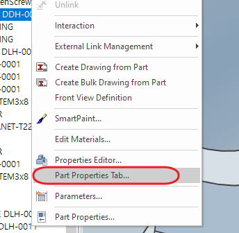
-
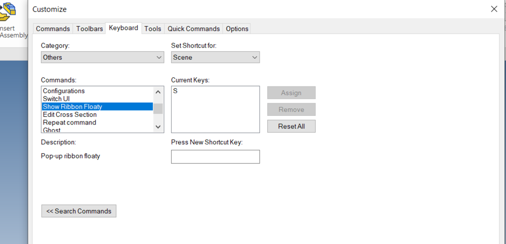
After updating my IronCAD, whenever i am clicking the button "S" which is shortcut of floaty ribbon button, I am only able to get these icons. How can I reset it so that i can all of the icons which use to show earlier...

-
 (ATLANTA, Ga.) December 19th, 2022 — IronCAD, the 3D CAD productivity platform of choice among metal fabricators and custom machinery manufacturers used by hundreds of thousands around the world, officially announced the release of IRONCAD 2023, which contains many exciting improvements and benefits that help customers drive innovation and move designs to production faster. IronCAD works directly with customers and strategically develops our new functionalities and product quality improvements targeted to strengthen existing customer satisfaction and compel new users in the equipment machinery and fabrication market to evaluate IronCAD’s benefits over the competition. Their most powerful release to date, IronCAD continues to strengthen their focus to build upon performance improvements expected in large assembly design, functionality improvements in the IronCAD 2D Detail Drawing Environment to be not only more competitive but also more productive, extend key modeling capabilities that continue to advance IronCAD’s flexibility and versatility needed to expand their market reach, and user interface improvements that continue to make IronCAD the easiest 3D CAD design product in this market space. Out of the many newly introduced improvements of IRONCAD 2023, some of the key features in this release include: Performance Improvements for Imported 3D Assemblies and 2D Drawing View Creation – Often when dealing with large assemblies, whether imported 3D data or even when creating 2D technical drawings, performance plays a critical factor in bringing in the data and placing it into production drawings. IronCAD 2023 has enhanced key functionality in these areas to reduce the import time and general interaction with the imported data while improving the view creation performance 5x to 10x. User Interface Improvements for Better Property Visibility and Collaboration – Improvements in the user interface extend throughout the IronCAD product portfolio to include a better understanding of objects and their visibility through the Object Viewer, Property List Viewer, and Property List editor. When collaborating with the IronCAD Web Viewer, users can visually measure designs sent to collaborators to understand the object’s size. Advanced Design Improvements Such as the New 3D Positional Constraint Types, 3D Curve Constraints, and Custom Structural Frames – New advanced design functions have been incorporated into IronCAD 2023 to give more power to users when creating complex designs. For example, new constraint types give users more control in parametric designs and the ability to drive 3D Curves that are leveraged in other operations such as surface designs. Customers also have more capabilities to create customized standards for structural frames to build parametric structural frame designs. IronCAD Drawing Improvements Including Column Grid Line Support, Custom Group Leader, and Quick Edit of Annotations from Catalog – New additions to the IronCAD Drawing Environment improve the overall design process giving users more capabilities while reducing steps to complete everyday tasks. Some examples include the new Column Grid Line annotation to display column lines from factories for precise placement, Group Leader line support to allow custom creation of annotations, and quick editing methods for annotations dropped from the catalog to list a few. CAXA Draft Improvements for Detailed 2D Drawing – Many improvements have been made in the CAXA DRAFT mechanical 2D Detailing Drawing environment extending its capabilities to offer powerful 2D detailing for users coming from other 2D applications and for detailing 3D Designs from IronCAD’s 3D design environment. “IronCAD 2023 has expanded all aspects of the IronCAD portfolio of design, engineering, and collaborations applications to streamline and accelerate the product development process in the equipment machinery and fabrication market.” Stated Cary O’Connor, V.P. of Marketing of IronCAD. “Performance, flexibility, and IronCAD’s versatility in design have all been incorporated in the new functionality making IronCAD 2023 a powerful but easy to uses application for users to accelerate their design production process” he continued. For a more extensive list of IRONCAD 2023 improvements and enhancements, click here. Try the newest version of IronCAD for free by navigating to https://www.ironcad.com/free-online-trial/ to start your free online trial. About IronCAD Based in Atlanta, Ga., IronCAD is a leading provider of 3D design productivity solutions that deliver the highest levels of customer satisfaction and productivity. Individual components of this solution can be used standalone, complementary within an existing design environment, or can be used together to collaborate effectively throughout the enterprise to extend productivity. IronCAD’s flagship product IRONCAD has won many industry awards for its innovative technology and leads the industry in its ease of use and design productivity. Thousands of customers worldwide use IronCAD to support their success. For more information about IronCAD, visit www.ironcad.com. View the full article
 -
What’s New in IronCAD Design Collaboration Suite 2023!
Cary OConnor posted a blog entry in IronCAD Corporate Website Blog
IronCAD Design Collaboration Suite 2023 Expanding CAD Productivity and Accelerating the Product Design Process It’s the most wonderful time of the year and IronCAD is excited to announce and share the latest release of IRONCAD 2023, which contains many exciting improvements and benefits that help customers drive innovation and move designs to production faster. IronCAD continues to strengthen its focus to build upon performance improvements common in large assembly design, functionality improvements in the IronCAD 2D Detail Drawing Environment to be not only more competitive but also more productive, extend key modeling capabilities that continue to advance IronCAD’s flexibility and versatility needed to expand their market reach and user interface improvements that continue to make IronCAD the easiest 3D CAD design product in the equipment machinery and fabrication market. See for yourself and learn more specific details about this release below: Quick Links Performance Improvements User Interface Improvements Advance Design Improvements Sheet Metal Design Improvements 2D Detailing in IronCAD Drawing Improvements CAXA DRAFT Drawing Updates Component and Collaboration Updates Performance Improvements Performance Improvements on IronCAD Drawing View Creation Working with larger data sets and using the Bulk Drawing Automatic Creation tool drastically improves IronCAD 2023 when creating the drawing views. Speed improvements from 5 to 10x have been implemented, making the overall time to layout drawing views much quicker in IronCAD 2023. Available in: http://www.ironcad.com/wp-content/uploads/2016/05/product_icon_ironcad-64x64.png Performance Improvements on Import 3D with Combine as Reference Often when dealing with large assemblies from customers, you can import data using the Combine as a reference option which creates a single part of the imported assembly. Performance improvements have been made to increase the model update on these large single parts that may generate many faces/surfaces. When importing, go to the Import Options and use primarily “Combine as Reference (or Import as Reference).” The combine option will have a more noticeable performance impact as it combines multiple parts to a single part (Import as Reference keeps individual parts). Available in: http://www.ironcad.com/wp-content/uploads/2016/05/product_icon_ironcad-64x64.pnghttp://www.ironcad.com/wp-content/uploads/2016/05/product_icon_inovate-64x64.pnghttp://www.ironcad.com/wp-content/uploads/2016/05/product_icon_draft-64x64.pnghttp://www.ironcad.com/wp-content/uploads/2016/05/product_icon_compose-64x64.png Import Step Files (without Repair Option Enabled) Importing STEP files without the Repair Option enabled has been improved to reduce multiple repair sequences. When importing, go to the Import Options and Turn off Repair Body for STEP files that experience long import times. Available in: http://www.ironcad.com/wp-content/uploads/2016/05/product_icon_ironcad-64x64.pnghttp://www.ironcad.com/wp-content/uploads/2016/05/product_icon_inovate-64x64.pnghttp://www.ironcad.com/wp-content/uploads/2016/05/product_icon_draft-64x64.png Box Selection on Large Assemblies Box selection with large assemblies with thousands of parts/assemblies has been greatly improved to reduce the overhead of selecting and highlighting objects. Both Right-to-Left and Left-to-Right Box selections have been improved in performance from minutes to a few seconds in many cases. Available in: http://www.ironcad.com/wp-content/uploads/2016/05/product_icon_ironcad-64x64.pnghttp://www.ironcad.com/wp-content/uploads/2016/05/product_icon_inovate-64x64.pnghttp://www.ironcad.com/wp-content/uploads/2016/05/product_icon_draft-64x64.pnghttp://www.ironcad.com/wp-content/uploads/2016/05/product_icon_compose-64x64.png User Interface Improvements Property List Browser With the recent addition of the Object Viewer, a new Property List Browser has been added to allow the visibility of the Properties of catalog items and selected objects sent to the Object Viewer from the Scene Browser. This improves the ability to clarify the desired object for use in catalog operations or scene operations. Located initially as a tab next to the Object Viewer, you can quickly select the Properties to see the content from the selected scene element or the selected catalog element. Available in: http://www.ironcad.com/wp-content/uploads/2016/05/product_icon_ironcad-64x64.pnghttp://www.ironcad.com/wp-content/uploads/2016/05/product_icon_inovate-64x64.pnghttp://www.ironcad.com/wp-content/uploads/2016/05/product_icon_draft-64x64.pnghttp://www.ironcad.com/wp-content/uploads/2016/05/product_icon_compose-64x64.png Catalog Single SmartPaint Property Object New ability to create a single property object using the Smart Paint Eye Dropper to collect Surface Finish, Material, and Text Properties into a single object that can be placed on other objects in the scene. Use the Smart Paint Eye Dropper to select an object. Right-click in the Catalog to drop and select All Properties. This will create a Folder with all the properties of the object. When you drop the folder, you can select which property to apply. Drill into the folder to select individual properties to apply to objects. Available in: http://www.ironcad.com/wp-content/uploads/2016/05/product_icon_ironcad-64x64.pnghttp://www.ironcad.com/wp-content/uploads/2016/05/product_icon_inovate-64x64.pnghttp://www.ironcad.com/wp-content/uploads/2016/05/product_icon_draft-64x64.png View Currently Set Front View Definitions New options to quickly view the Front View Definition on any selected object to determine its location and if the object has the definition defined. Available in: http://www.ironcad.com/wp-content/uploads/2016/05/product_icon_ironcad-64x64.pnghttp://www.ironcad.com/wp-content/uploads/2016/05/product_icon_inovate-64x64.pnghttp://www.ironcad.com/wp-content/uploads/2016/05/product_icon_draft-64x64.png Multiple Apply Front View Definition New ability to apply the front view definition to a selection of parts based on Anchor location of local/global orientation. This can dramatically increase the speed of placing the front view definition in the Bulk View Creation Process. Available in: http://www.ironcad.com/wp-content/uploads/2016/05/product_icon_ironcad-64x64.pnghttp://www.ironcad.com/wp-content/uploads/2016/05/product_icon_inovate-64x64.pnghttp://www.ironcad.com/wp-content/uploads/2016/05/product_icon_draft-64x64.png Share Web Viewer Support for Graphical Measurements The Share Web Viewer now supports basic measurements for users to get rough dimension sizes for models quickly. Note: The measurements are based on the graphical data and are not precise as measuring in IronCAD Solid Modeling applications. Set Rotation Reference New option on the Right-click of the scene to set a rotation reference when using the Middle Mouse orbit. Once selected, pick a point or location on a part in the scene. All rotations will revolve around that location. Right-click in the scene for options Remove the Rotation Reference. This command can also be set to a Keyboard shortcut if desired. Available in: http://www.ironcad.com/wp-content/uploads/2016/05/product_icon_ironcad-64x64.pnghttp://www.ironcad.com/wp-content/uploads/2016/05/product_icon_inovate-64x64.pnghttp://www.ironcad.com/wp-content/uploads/2016/05/product_icon_draft-64x64.pnghttp://www.ironcad.com/wp-content/uploads/2016/05/product_icon_compose-64x64.png Set Transparency on Selected A new Right-click menu option to quickly set the currently selected object to Transparent. Selection actions still works on these objects, but this is a quick way to see through the various objects without completely hiding them. Right-click for options to remove the transparency setting on all objects in the scene. Available in: http://www.ironcad.com/wp-content/uploads/2016/05/product_icon_ironcad-64x64.pnghttp://www.ironcad.com/wp-content/uploads/2016/05/product_icon_inovate-64x64.pnghttp://www.ironcad.com/wp-content/uploads/2016/05/product_icon_draft-64x64.pnghttp://www.ironcad.com/wp-content/uploads/2016/05/product_icon_compose-64x64.png Scene Level Section Tool A new section tool has been added to the scene to allow multiple plane sections and isolation section areas. This section is not an object in the scene browser and is geared only for visibility in the scene. Multiple sections can be created and stored with names that you can quickly toggle between. This command is located on the Status Bar at the bottom of the Scene window. Available in: http://www.ironcad.com/wp-content/uploads/2016/05/product_icon_ironcad-64x64.pnghttp://www.ironcad.com/wp-content/uploads/2016/05/product_icon_inovate-64x64.pnghttp://www.ironcad.com/wp-content/uploads/2016/05/product_icon_draft-64x64.png New Smart Motion Editor New improvements have been made to redesign the Smart Motion Editor to match more modern animation UI’s. Common controls are added to the editor to make it a single location to modify, run and export animations. Add Viewports (and Keys) to control the scene rotation timeline. This improvement helps streamline the creation of Animations. Available in: http://www.ironcad.com/wp-content/uploads/2016/05/product_icon_ironcad-64x64.pnghttp://www.ironcad.com/wp-content/uploads/2016/05/product_icon_inovate-64x64.pnghttp://www.ironcad.com/wp-content/uploads/2016/05/product_icon_draft-64x64.pnghttp://www.ironcad.com/wp-content/uploads/2016/05/product_icon_compose-64x64.png Pin File Favorites Added to Main Menu Recent List The new “Pin Favorites” from the recently opened file list in the Welcome dialog has now been added to the Main Menu recent list as well to make it convenient to access the recent favorites list in multiple locations. Available in: http://www.ironcad.com/wp-content/uploads/2016/05/product_icon_ironcad-64x64.pnghttp://www.ironcad.com/wp-content/uploads/2016/05/product_icon_inovate-64x64.pnghttp://www.ironcad.com/wp-content/uploads/2016/05/product_icon_draft-64x64.pnghttp://www.ironcad.com/wp-content/uploads/2016/05/product_icon_compose-64x64.png Delete Key to Clear Sizebox Values Users wanted more control over the floating Sizebox edit box. The old behavior, when hitting the Delete Key, was the shape would delete from the scene. This is not always expected with new users. Most new users expected the number inside of the sizebox edit box to be deleted if they had recently made a change to it. Now, if you pull a handle and then hit delete, the delete behavior will delete the value in the edit box to allow you to type over the displayed full value. Available in: http://www.ironcad.com/wp-content/uploads/2016/05/product_icon_ironcad-64x64.pnghttp://www.ironcad.com/wp-content/uploads/2016/05/product_icon_inovate-64x64.pnghttp://www.ironcad.com/wp-content/uploads/2016/05/product_icon_draft-64x64.pnghttp://www.ironcad.com/wp-content/uploads/2016/05/product_icon_compose-64x64.png Advanced Design Improvements New 3D Curve Constraints 3D Curves now support adding constraints to drive the 3D Curves parametrically. This is a major improvement and opens the possibilities for more complex path generation for surfaces and sweeps. Using the Structure Part, you can fully drive the structured part using the 3D Curves. Innovative Parts – make sure to add the constraint to the 3D Curves under the generated features that consume the 3D Curve data (not on the source 3D curve). Available in: http://www.ironcad.com/wp-content/uploads/2016/05/product_icon_ironcad-64x64.pnghttp://www.ironcad.com/wp-content/uploads/2016/05/product_icon_inovate-64x64.png New 3D Positional Constraint Types and UI Improvements to the Positional Constraints have been added, such as Symmetry, Width, and Path constraints. In addition, the UI has been improved to separate Basic and Advance Constraint types and to reduce duplicate constraints such as Mate/Align, which is the same as Coincident with Alignment Options. Available in: http://www.ironcad.com/wp-content/uploads/2016/05/product_icon_ironcad-64x64.pnghttp://www.ironcad.com/wp-content/uploads/2016/05/product_icon_inovate-64x64.png Copy as Link Body Mirror A very powerful new option on the Part/Assembly Mirror Creation on the TriBall allows for a Linked Body to be created from the original part/assembly however it is a copy in such that you can change the color and make other changes from the original part/assembly. When updates are made to the source geometry, the body will update with these changes. Available in: http://www.ironcad.com/wp-content/uploads/2016/05/product_icon_ironcad-64x64.pnghttp://www.ironcad.com/wp-content/uploads/2016/05/product_icon_inovate-64x64.pnghttp://www.ironcad.com/wp-content/uploads/2016/05/product_icon_draft-64x64.png Copy/Link Body Command at Current Location Improvements to the Copy/Link Body command to maintain the current location of the copied/linked body to streamline the positioning when placed in the other part. Available in: http://www.ironcad.com/wp-content/uploads/2016/05/product_icon_ironcad-64x64.png Linked Body Open File Containing Folder When you have linked bodies, you can now right-click on the linked BREP and have access to open the containing folder where the linked file exits. This saves time locating the file location and opening outside of the product. Available in: http://www.ironcad.com/wp-content/uploads/2016/05/product_icon_ironcad-64x64.pnghttp://www.ironcad.com/wp-content/uploads/2016/05/product_icon_inovate-64x64.png Specific Removal Commands Users from other CAD systems are familiar with Add Extrude, Spin, etc, and Remove Extrude, Spin, etc. IronCAD typically has these inside the same command. Now you can have individual commands on your Ribbon Bar to simplify the process. Available in: http://www.ironcad.com/wp-content/uploads/2016/05/product_icon_ironcad-64x64.pnghttp://www.ironcad.com/wp-content/uploads/2016/05/product_icon_inovate-64x64.png Structure Part Only Design UI Template A new command has been added to automatically create a new Structured Part-only template that builds a new Ribbon Bar UI built for part commands only. The UI is modified to prevent Assembly creation (or drop of assemblies into the scene). This UI is designed to give a feel of traditional CAD applications to create parts and is useful for singular part design. By default, this is not added to the Ribbon Bar. Available in: http://www.ironcad.com/wp-content/uploads/2016/05/product_icon_ironcad-64x64.png Structure Part Body Replace Support for Configurations When replacing the BREP body (created from Import or a Copy Body operation) inside a Structured Part, when replacing the body and selecting Structured Part ICS file that has configurations of different body states, the replace will allow you to set the desired configuration and load the appropriate body representation for the configuration. Available in: http://www.ironcad.com/wp-content/uploads/2016/05/product_icon_ironcad-64x64.png Property Template Improvements and Property Tab Editor Improvements have been made to the Property Template capabilities to add System Properties such as Part Number, Mass, etc. in the Template. In addition, a Property Tab Editor is available on Parts/Assemblies to edit these in a common location. Users with IronCAD Mechanical typically used the ProActive BOM, but now can achieve an editing style of the common properties for users without IronCAD Mechanical. For the Property Tab Editor to populate, the newly created parts/assemblies need to have property templates applied in the Tools/Options/Default Property Settings. Available in: http://www.ironcad.com/wp-content/uploads/2016/05/product_icon_ironcad-64x64.pnghttp://www.ironcad.com/wp-content/uploads/2016/05/product_icon_inovate-64x64.pnghttp://www.ironcad.com/wp-content/uploads/2016/05/product_icon_draft-64x64.png Apply Cosmetic Threads to Holes Useful new utility for Imported Data to apply Thread data to Imported Brep models with holes based on standards. This can quickly apply thread data to multiple-size holes on a part/selection that is not transferred during import operations. You can manually place threads as well to a single selection or use the Auto Detect to create multiples on an entire part based on available options. Available in: http://www.ironcad.com/wp-content/uploads/2016/05/product_icon_ironcad-64x64.pnghttp://www.ironcad.com/wp-content/uploads/2016/05/product_icon_inovate-64x64.png Replace Parts Remember Self-Contained Parameter Expressions Using the Ctrl-Right-Click from a Catalog to replace a part with self-contained parameters (that refer to itself) will now be maintained/updated on the replace command. This is supported for parts/assemblies stored in catalogs that will replace the same part in the scene. Replacing other parts, this command may not fully find identical parameter references. Available in: http://www.ironcad.com/wp-content/uploads/2016/05/product_icon_ironcad-64x64.pnghttp://www.ironcad.com/wp-content/uploads/2016/05/product_icon_inovate-64x64.png Property Data from Native CAD Format Native CAD files such as Inventor, SolidWorks, UG, CATIA V5 have many properties for parts and assemblies. Issues occurred that if we import assembly files, the properties are only shown at the assembly level. Also, many properties only have English names when importing them. Users in a different language, they want to see the properties in their native language. For 2023, provided a way to modify a map to convert the English property name to the localized name by using a customization file IC_Import_UDA.xml located in C:\Program Files\IronCAD\2022\AppData\”Lang”\Import. ”Lang” is the setting to control the language to use. For English, it is en-us, For traditional Chinese, it is zh-tw for example. IC_Import_UDA.xml format is below: <?xml version=”1.0″ encoding=”utf-8″?> <UDALocalName Version=”1.0″> <NameMap Name=”Creation Date” Localization = “建立日期”/> <NameMap Name=”Design State” Localization = “設計狀態”/> <NameMap Name=”Designer” Localization = “設計者”/> <NameMap Name=”File Subtype” Localization = “檔案子類型”/> <NameMap Name=”Location” Localization = “路徑”/> <NameMap Name=”Poisson’s Ratio” Localization = “蒲松比”/> <NameMap Name=”Revision Number” Localization = “修訂號”/> <NameMap Name=”Specific Heat” Localization = “比熱”/> <NameMap Name=”Thermal Conductivity” Localization = “導熱係數”/> <NameMap Name=”Thermal Expansion Coefficient” Localization = “熱膨脹係數”/> <NameMap Name=”Ultimate Tensile Strength” Localization = “極限抗拉強度”/> <NameMap Name=”Yield Strength” Localization = “屈服強度”/> <NameMap Name=”Young’s Modulus” Localization = “楊式模量”/> </UDALocalName> If the system finds the name map, then it will replace the Name by the localization name. Users can add new entries or delete any entries as needed. Users can also leave the localization blank to not replace the name. Available in: http://www.ironcad.com/wp-content/uploads/2016/05/product_icon_ironcad-64x64.pnghttp://www.ironcad.com/wp-content/uploads/2016/05/product_icon_inovate-64x64.pnghttp://www.ironcad.com/wp-content/uploads/2016/05/product_icon_draft-64x64.png Selection Tolerance for Ctrl-Alt Click for Attachment Points When multiple attachment points are in close proximity, it is difficult to select the attachments. A new tolerance based on the selected aperture setting has been added to select nearby attachment points when using the Ctrl-Alt-Left-Click selection list. Available in: http://www.ironcad.com/wp-content/uploads/2016/05/product_icon_ironcad-64x64.pnghttp://www.ironcad.com/wp-content/uploads/2016/05/product_icon_inovate-64x64.pnghttp://www.ironcad.com/wp-content/uploads/2016/05/product_icon_draft-64x64.png Custom Properties as Text Parameter New capabilities have been added to use the Formula behaviors for Custom Properties to link to other Custom Properties values. Using the custom property name, you can construct a formula (=$CustomProperty&) to pull from other properties that can be text or parameter-driven strings. Available in: http://www.ironcad.com/wp-content/uploads/2016/05/product_icon_ironcad-64x64.pnghttp://www.ironcad.com/wp-content/uploads/2016/05/product_icon_inovate-64x64.pnghttp://www.ironcad.com/wp-content/uploads/2016/05/product_icon_draft-64x64.png Common Components Detected In Bulk View PB When using Common Component catalog items that have drawings associated with them, the property browser has been updated to detect the existence of the associated drawing to avoid placing a Bulk View Template on the part/assembly. Available in: http://www.ironcad.com/wp-content/uploads/2016/05/product_icon_ironcad-64x64.png Sheet Metal Improvements Default Bend Allowance Setting for New Bends Added Users now have the ability to set the default Bend Allowance Setting when creating new features. In this release, there are 3 enhancements related to Bend Allowance: In Tools-Option | Sheet Metal Settings, we added a new feature bend allowance type. There are 6 bend allowance types shown below. When creating new Bend, Sketch Bend, and Punch Bend, the feature’s bend allowance will be set based on the default. Bend Deduction of Part for Bend Feature now updates when Bend Deduction in part property changes. Added Bend Deduction of Part for both Sketch Bend and Punch Bend Features. Available in: http://www.ironcad.com/wp-content/uploads/2016/05/product_icon_ironcad-64x64.png Deletion of Linked Folded Sheet Metal Retains Unfold When you have a folded sheet metal part (that has an unfolded part) and link it multiple times in the scene, deleting one instance of the sheet metal part will not delete the unfolded part now but transfer it to one of the remaining linked instances. This auto-detect functionality to relink is added in 2023. Available in: http://www.ironcad.com/wp-content/uploads/2016/05/product_icon_ironcad-64x64.pnghttp://www.ironcad.com/wp-content/uploads/2016/05/product_icon_inovate-64x64.png Corner Relief Option to Support Inside/Outside Closed Conditions When you create a sheet metal bend and move the bends stock segment outside using the corner relief handles, it will automatically add the closed corner condition. However, this was more difficult if the stock was moved inside. Now in this release, if you move with corner relief with the Ctrl-Left-Click drag, it will create the inner corner relief. Available in: http://www.ironcad.com/wp-content/uploads/2016/05/product_icon_ironcad-64x64.pnghttp://www.ironcad.com/wp-content/uploads/2016/05/product_icon_inovate-64x64.png IronCAD Drawing Improvements Column Grid Line Support Ability to create X/Y column line callouts in the drawing to reference structural columns with the ability to dimension to references. Common for reference annotations in structural/mechanical design/layout applications. This new command is located on the Annotation Ribbon under the Reference Group. Styles are available in the Style Manager to set the label, Size, Colors, and line types. The Origin location for the column is pulled from the global coordinate 0,0,0 location in the scene. You can use local coordinates as well to define a specific origin location relative to your model. Available in: http://www.ironcad.com/wp-content/uploads/2016/05/product_icon_ironcad-64x64.png Circular Hole Symbol for Dowel Callouts New Command to create circular hole symbols used to callout customer-specific dowel types. Users can select the standard types and combine types to make custom callout types for their specific dowel references. This is a style object that can be set in the Styles & Layers dialog. Available in: http://www.ironcad.com/wp-content/uploads/2016/05/product_icon_ironcad-64x64.png Groups Support for Leaders User-defined group shapes can now add leaders to allow the custom creation of symbols that can be stored and reused from catalogs. Simply right-click on the group to access the option to add a leader line. Available in: http://www.ironcad.com/wp-content/uploads/2016/05/product_icon_ironcad-64x64.png Section View Dynamic Switch Direction Based on the user’s placement location of the section view, the section direction can dynamically update to give the correct section view. This is an option that can be enabled/disabled. Available in: http://www.ironcad.com/wp-content/uploads/2016/05/product_icon_ironcad-64x64.png Dynamic Text Box Sizing on Horizontal/Vertical Toggles When toggling between horizontal and Vertical placement for Text Boxes with Leaders, the bounding box will automatically adjust to maintain a similar size and position of the text elements in either location. Available in: http://www.ironcad.com/wp-content/uploads/2016/05/product_icon_ironcad-64x64.png Align Text Boxes to Selected Edge New ability to align a text box to a selected edge to remove the complexity of knowing the angle at which to rotate a text box. Available in: http://www.ironcad.com/wp-content/uploads/2016/05/product_icon_ironcad-64x64.png Edit Scene Focus to Current View Selection List New option to set the scene in the hidden part state from the view to reduce confusion and allow quick editing of the desired view in the Selection List view state. Available in: http://www.ironcad.com/wp-content/uploads/2016/05/product_icon_ironcad-64x64.png Box Select Centerline Improvement Improvements have been made to avoid the creation on hidden arcs/circles during the Box Selection Centerline Creation. If Hidden Edges are displayed in the view, the annotations will be created on the hidden elements. Available in: http://www.ironcad.com/wp-content/uploads/2016/05/product_icon_ironcad-64x64.png Thread Quantity Callout Based on Thread Type New options have been added for the Auto Hole Quantity callout to be based on the Thread Type versus the Linked Instances. This improves the detailing process to callout all holes of the same thread type directly. Available in: http://www.ironcad.com/wp-content/uploads/2016/05/product_icon_ironcad-64x64.png Hide Unselected for Threads When transferring thread callouts, a user may only want to see certain threads or especially when using the Auto hole count on threads, they usually just one representative one that shows the count of the total number. To support this, users can select the representative holes and right-click select “Hide Unselected” to see only the holes needed for display. This works to hide thread of holes that are linked. Available in: http://www.ironcad.com/wp-content/uploads/2016/05/product_icon_ironcad-64x64.png Spell Checker Support for Uppercase The ICD Spell Checker has been improved to support Uppercase text, which is common in technical detailing. Available in: http://www.ironcad.com/wp-content/uploads/2016/05/product_icon_ironcad-64x64.png Quick Edit of Annotations from Catalog If an annotation item in a catalog is dropped out using the Right-Click Drag, on release the properties of the annotation type will appear to allow quick editing of the properties. For example, a Datum Callout could automatically pop-up the properties to quickly change the tag. Available in: http://www.ironcad.com/wp-content/uploads/2016/05/product_icon_ironcad-64x64.png View “Use Part Colors for Edges” Support Export to DWG When using the “Use Part Color for Edges” in views, exporting to DWG will now maintain these colors for improved transfer of settings from ICD to DWG. Available in: http://www.ironcad.com/wp-content/uploads/2016/05/product_icon_ironcad-64x64.png Optional Space Setting Between Dimension/Tolerance A new setting has been added to the tolerance property page to allow a user-inputted space between the dimension value and the tolerance display. Available in: http://www.ironcad.com/wp-content/uploads/2016/05/product_icon_ironcad-64x64.png Linked Page Text Time Option When using the Linked Page Text options in text, you can add Links to date such as Created Date. You now have the option to show/hide the Timestamp as part of that date text link. Available in: http://www.ironcad.com/wp-content/uploads/2016/05/product_icon_ironcad-64x64.png Snap to Edge in Section View In section views, sometimes the section-hatching geometry displays on top of the real geometry preventing the dimension creation to a curve. Using the Spacebar during dimension creation, a new option is provided to Snap to Geometry Behind the Section to allow the dimension to occur. Available in: http://www.ironcad.com/wp-content/uploads/2016/05/product_icon_ironcad-64x64.png Export Sheet Range to DWG New options have been added to the ICD export to DWG to allow you to specify the specific sheets to export (range). Available in: http://www.ironcad.com/wp-content/uploads/2016/05/product_icon_ironcad-64x64.png CAXA DRAFT Improvements Section View Support for Depth Ability to create a section view based on a depth setting and adjust the depth dynamically after creation. Available in: http://www.ironcad.com/wp-content/uploads/2016/05/product_icon_ironcad-64x64.pnghttp://www.ironcad.com/wp-content/uploads/2016/05/product_icon_draft-64x64.png PDF File Import Improvements You can now import vector geometry, solid fills, raster images, and TrueType fonts in a PDF file into the current CAXA DRAFT drawing, and retain features such as proportions, layers, line types, and colors from the source PDF file. Available in: http://www.ironcad.com/wp-content/uploads/2016/05/product_icon_ironcad-64x64.pnghttp://www.ironcad.com/wp-content/uploads/2016/05/product_icon_draft-64x64.png PDF Export Enhancements Exporting a CAXA DRAFT drawing using Export to PDF will now support vector curves which will greatly reduce the file size. In addition, TrueType fonts are supported now. Available in: http://www.ironcad.com/wp-content/uploads/2016/05/product_icon_ironcad-64x64.pnghttp://www.ironcad.com/wp-content/uploads/2016/05/product_icon_draft-64x64.png Smart Printing/Plot (Area) You can print multiple drawings in the current drawing after box selection and support the conversion to PDF, JPG, PNG, TIF and other format files. Available in: http://www.ironcad.com/wp-content/uploads/2016/05/product_icon_ironcad-64x64.pnghttp://www.ironcad.com/wp-content/uploads/2016/05/product_icon_draft-64x64.png New Import Support for DWT file You can open a DWT format file directly in CAXA DRAFT. Available in: http://www.ironcad.com/wp-content/uploads/2016/05/product_icon_ironcad-64x64.pnghttp://www.ironcad.com/wp-content/uploads/2016/05/product_icon_draft-64x64.png Enhance DWG Type Identification Special object data that supports the identification of AutoCAD, including title bars, serial numbers, schedules, etc. Using an XML, certain data can be transferred directly into CAXA DRAFT data structures during the import/open. Available in: http://www.ironcad.com/wp-content/uploads/2016/05/product_icon_ironcad-64x64.pnghttp://www.ironcad.com/wp-content/uploads/2016/05/product_icon_draft-64x64.png Rectangle Curve by Center Point You can now create a Rectangle using the center point and size. Available in: http://www.ironcad.com/wp-content/uploads/2016/05/product_icon_ironcad-64x64.pnghttp://www.ironcad.com/wp-content/uploads/2016/05/product_icon_draft-64x64.png Enhanced Fillet Function Support for picking up two parallel lines to place a full corner between the parallel lines. Available in: http://www.ironcad.com/wp-content/uploads/2016/05/product_icon_ironcad-64x64.pnghttp://www.ironcad.com/wp-content/uploads/2016/05/product_icon_draft-64x64.png Enhanced Hole / Shaft Function Support both start and end diameter with value 0. Available in: http://www.ironcad.com/wp-content/uploads/2016/05/product_icon_ironcad-64x64.pnghttp://www.ironcad.com/wp-content/uploads/2016/05/product_icon_draft-64x64.png Curve Array Support For Distance Spacing Available in: http://www.ironcad.com/wp-content/uploads/2016/05/product_icon_ironcad-64x64.pnghttp://www.ironcad.com/wp-content/uploads/2016/05/product_icon_draft-64x64.png New Isolation Command Feature Ability to Hide/Isolate selected elements in the drawing to allow focus on selected areas of a drawing. The command is found on the right-click menu after selecting various elements. Available in: http://www.ironcad.com/wp-content/uploads/2016/05/product_icon_ironcad-64x64.pnghttp://www.ironcad.com/wp-content/uploads/2016/05/product_icon_draft-64x64.png User-Created Table Export Support User-created tables using lines, text, etc., can be selected and exported to xls, xlsx table files. Available in: http://www.ironcad.com/wp-content/uploads/2016/05/product_icon_ironcad-64x64.pnghttp://www.ironcad.com/wp-content/uploads/2016/05/product_icon_draft-64x64.png Items Now Support Split Serial Numbers Supports the splitting of consolidated numbers into separate numbers. Available in: http://www.ironcad.com/wp-content/uploads/2016/05/product_icon_ironcad-64x64.pnghttp://www.ironcad.com/wp-content/uploads/2016/05/product_icon_draft-64x64.png Surface Roughness Dimension Enhancement Add the Majority Symbol option to support the latest standard requirements for the surface finish for GB 131-93. The symbol option is for non-leader-based surface roughness symbols. Available in: http://www.ironcad.com/wp-content/uploads/2016/05/product_icon_ironcad-64x64.pnghttp://www.ironcad.com/wp-content/uploads/2016/05/product_icon_draft-64x64.png Arc length Annotation Improvements Support for the whole segment or picked partial arcs. Available in: http://www.ironcad.com/wp-content/uploads/2016/05/product_icon_ironcad-64x64.pnghttp://www.ironcad.com/wp-content/uploads/2016/05/product_icon_draft-64x64.png File Tab Enhancements Multiple features are added to the file tab right-click pop-up, including opening, saving all, closing all, closing others, and copying the full file path. Available in: http://www.ironcad.com/wp-content/uploads/2016/05/product_icon_ironcad-64x64.pnghttp://www.ironcad.com/wp-content/uploads/2016/05/product_icon_draft-64x64.png File Open Remembers Previous Path After opening a file successfully, start the open dialog box the next time to automatically locate and select the last opened file location. Available in: http://www.ironcad.com/wp-content/uploads/2016/05/product_icon_ironcad-64x64.pnghttp://www.ironcad.com/wp-content/uploads/2016/05/product_icon_draft-64x64.png Text Search (Find) and Replacement Enhancement Results now show quantity statistics to understand the number of instances to replace/change. Available in: http://www.ironcad.com/wp-content/uploads/2016/05/product_icon_ironcad-64x64.pnghttp://www.ironcad.com/wp-content/uploads/2016/05/product_icon_draft-64x64.png Property Matching Adds Support for Tolerances Available in: http://www.ironcad.com/wp-content/uploads/2016/05/product_icon_ironcad-64x64.pnghttp://www.ironcad.com/wp-content/uploads/2016/05/product_icon_draft-64x64.png Table Supports the .xlsx Format When you insert a table object, you can link the xls and xlsx format files to create the table directly. After selecting the existing table object, make a xls or xlsx file through the right-click menu Output. Available in: http://www.ironcad.com/wp-content/uploads/2016/05/product_icon_ironcad-64x64.pnghttp://www.ironcad.com/wp-content/uploads/2016/05/product_icon_draft-64x64.png Gallery Update Update 232 figure symbol standards and data involving the categories of nuts, studs, bolts, screws, etc. The current graph library contains 53 large classes and 5346 subclasses. Available in: http://www.ironcad.com/wp-content/uploads/2016/05/product_icon_ironcad-64x64.pnghttp://www.ironcad.com/wp-content/uploads/2016/05/product_icon_draft-64x64.png Image Library Enhancements Add the function of “Non-parametric Symbol”, and support to pick up splines, pictures, and other objects as non-parametric graph internal data. Available in: http://www.ironcad.com/wp-content/uploads/2016/05/product_icon_ironcad-64x64.pnghttp://www.ironcad.com/wp-content/uploads/2016/05/product_icon_draft-64x64.png Others After setting the frame, the frame, title bar, top bar, and bottom bar of the new sheet will keep the options of the last set. Optimize the weight calculator, text search, replacement, filling in a schedule, and other functions to view the graphics or execute new commands when opening the dialog box. Resolve PAT partial data-compatible errors. Improved efficiency in graphic editing with more text. Available in: http://www.ironcad.com/wp-content/uploads/2016/05/product_icon_ironcad-64x64.pnghttp://www.ironcad.com/wp-content/uploads/2016/05/product_icon_draft-64x64.png Component and Collaboration Updates Support for the Latest Translator Versions IronCAD’s Native Translator has been updated for the formats listed below for formats such as SolidWorks, Inventor, Pro/E, Unigraphics, and Catia. CATIA V5: V5R8 – V5–6R2022 Pro/E (CREO): 16 – Creo 9.0 UG NX: 11 – NX 2206 Inventor: V11 – V2023 SolidWorks: 98 – 2022 SolidEdge: V18 – SE 2022 JT Import: 8 – 10.2, 10.3, 10.5, 10.6, and 10.7, And Graphics Import IFC: IFC2x3, IFC4 Rhino: V2-7 Available in: http://www.ironcad.com/wp-content/uploads/2016/05/product_icon_ironcad-64x64.pnghttp://www.ironcad.com/wp-content/uploads/2016/05/product_icon_inovate-64x64.pnghttp://www.ironcad.com/wp-content/uploads/2016/05/product_icon_draft-64x64.pnghttp://www.ironcad.com/wp-content/uploads/2016/05/product_icon_compose-64x64.png Multiphysics for IronCAD Multiphysics for IronCAD has been updated to the latest version. Details will be shared in a blog post for Multiphysics for IronCAD 2023. Available in: http://www.ironcad.com/wp-content/uploads/2016/05/product_icon_ironcad-64x64.pnghttp://www.ironcad.com/wp-content/uploads/2016/05/product_icon_inovate-64x64.png IronCAD Mechanical Updates to the latest version of IronCAD Mechanical. Details will be shared in a blog post for IronCAD Mechanical 2023. Available in: http://www.ironcad.com/wp-content/uploads/2016/05/product_icon_ironcad-64x64.pnghttp://www.ironcad.com/wp-content/uploads/2016/05/product_icon_inovate-64x64.png View the full article -
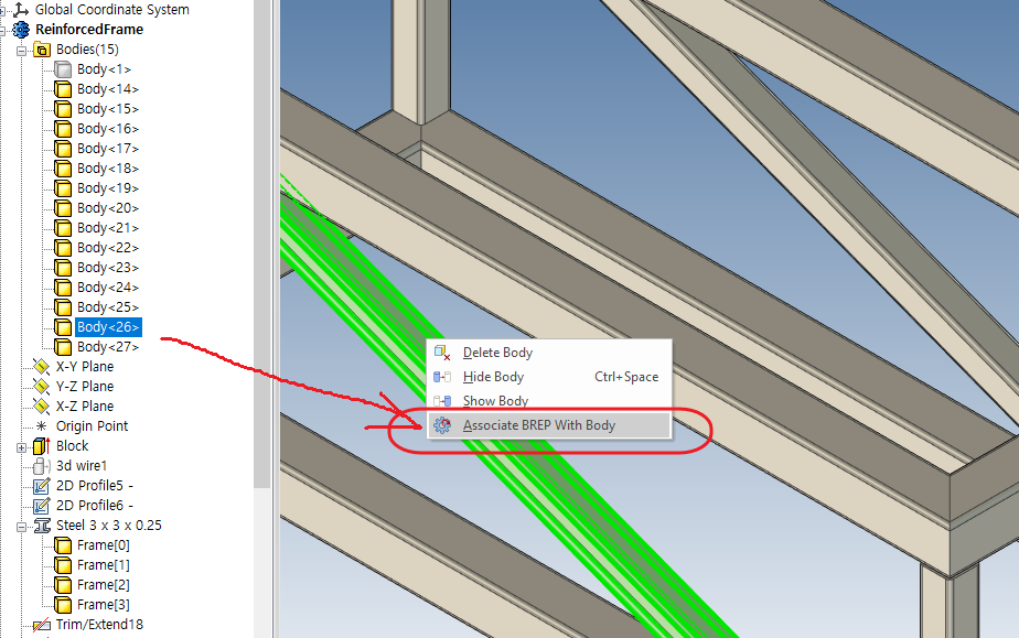
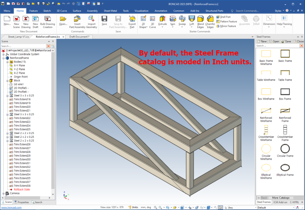
Hi We are suggesting users not to use Steel Frame for the reasons outlined below. I'm sure there's a workaround, but if anyone knows of one, I'd be very grateful. 1. By default, Steel Frames Catalogs are in Inch, how can I set it to JIS or KS? 2. How do I create a part drawings when designing with a steel frame? 3. How do I create a bulk drawings when designing with a steel frame? 4. How do I know that Body<26> in the Bodies Tree is matched with the generated file when I create a part using Associate BREP With Body Menu?(steel_frame-2.png) Thanks.