tgjang
-
Posts
447 -
Joined
-
Last visited
Content Type
Profiles
Forums
Blogs
Downloads
Articles
Gallery
Everything posted by tgjang
-

What are the reserved words for IronCAD and CAXA Draft?
tgjang replied to tgjang's topic in General Discussion
Thanks. Malcolm. Malcolm's information about ICAXA Draft is very useful because there are no detailed documents on ICAXA Draft, either on the Internet or anywhere else. Thank you very much, Malcolm. ^^ -
Hi I want to know the reserved words (attributes) used in CAXA Draft drawings, such as Part Number, Part Name, Part Quantity, and Material. I am not sure which words are pre-reserved and IronCAD users need to be aware of them in order to use them for drawing BOM, Title Block, and other purposes. Thanks.


-
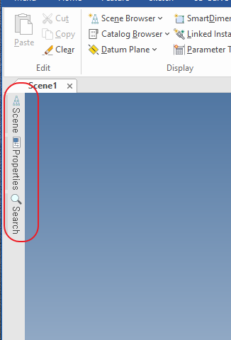
Thank you very much Kevin. Now It is all reset. ^^
-
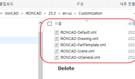
Hi I'm trying to fix the IronCAD Scene Brower basically. I do not know why, but if you always create a new scene, the scene tree window is hidden. I deleted the xml file under the Roaming/ironcad/Ironcad/25.0/en-us/customization directory and it's still the same. Thanks.
-
caxa draft text > explode text > copy exploded text profile to IronCAD extrude section plan > extrude it. lee_meng_che.ics

-
Text File Import Questions for Creating a 3D Surface
tgjang replied to tgjang's topic in General Discussion
Thank you very much. Carry. ^^ -
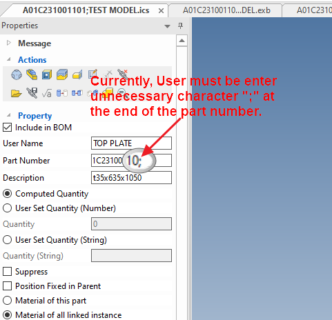
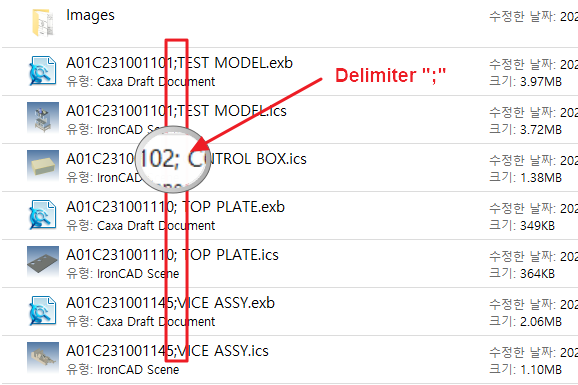
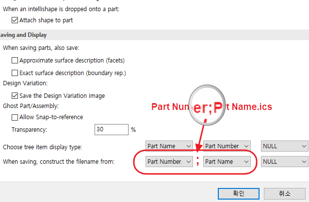
Question. When saving, construct the filename.
tgjang replied to tgjang's topic in General Discussion
Thanks Cary for reply. Windows OS does not allow many characters, as Cary suggests. These characters are usually not appropriate as a delimiter between CAD Part Number and Part Name, as they are often used in drawing BOMs, such as "x" in "5x6x10" or "SHEET_LEFT" or "SHEET-05". In the PLM system, it can be managed only by dividing it into Dilimiter with letters that are not often written in the drawing. Therefore, the ";" character is most appropriate. To cover Kim's opinion, IronCAD allow the user to enter the character he wants directly into the Text Field. Thanks.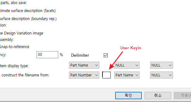
-
Thank you very much. Kevin, Cary. If IronCAD can create Rip and development plans from Shelled solid, it will save a lot of time on sheet metal design. ^^;
-
CAXA Draft - dumb question! - how do you do a fillet or a chamfer
tgjang replied to HDEAR's topic in General Discussion
Fillet : Use the shot cut key "f" > "space bar". Fillet, Chamfer : "cn " > "Spacebar" Chamfer : cha > "space bar" -
Hi We are developing a PLM system and would like to combine the IronCAD File name with "Part Number ; Part Name". If the part number does not include a delimiter such as ";", the part number cannot be distinguished from the file name. I would like to know how to put ";" between Part Number and Part Name. Thanks
-
Text File Import Questions for Creating a 3D Surface
tgjang replied to tgjang's topic in General Discussion
It solved. Ibl file format is exatly same as Creo. Test_ibl.ibl

-
Hi I would like to use IronCAD to design the pump impeller. (To sell the IronCAD) In order to design the impeller, whether I develop the design program using excel or Python, I need to create coordinate data using text file.dat, import it, create a 3D curve first, and create a surface. Please let me know which menu to use with the data format. 1.Coordinate data format The File Description # X and Z -41 -90 -10 -41 170 -10 -20 170-10 2012 - 10 270 - 10. 2. Coordinate data format Point. x1,y1,z1 x2,y2,z2 &. xn,yn,zn Line! x1,y1,z1 x2,y2,z2 &. xn,yn,zn Spline n x1,y1,z1 x2,y2,z2 &. xn,yn,zn EOF
-
Hi. I would to make a sheet metal part by tearing the edge of the same model as the attached picture. In Creo, it's like a video that attaches sheet metal. Does it possible? Thanks. Creo_Sheet_Metal_edited(3).mp4

-
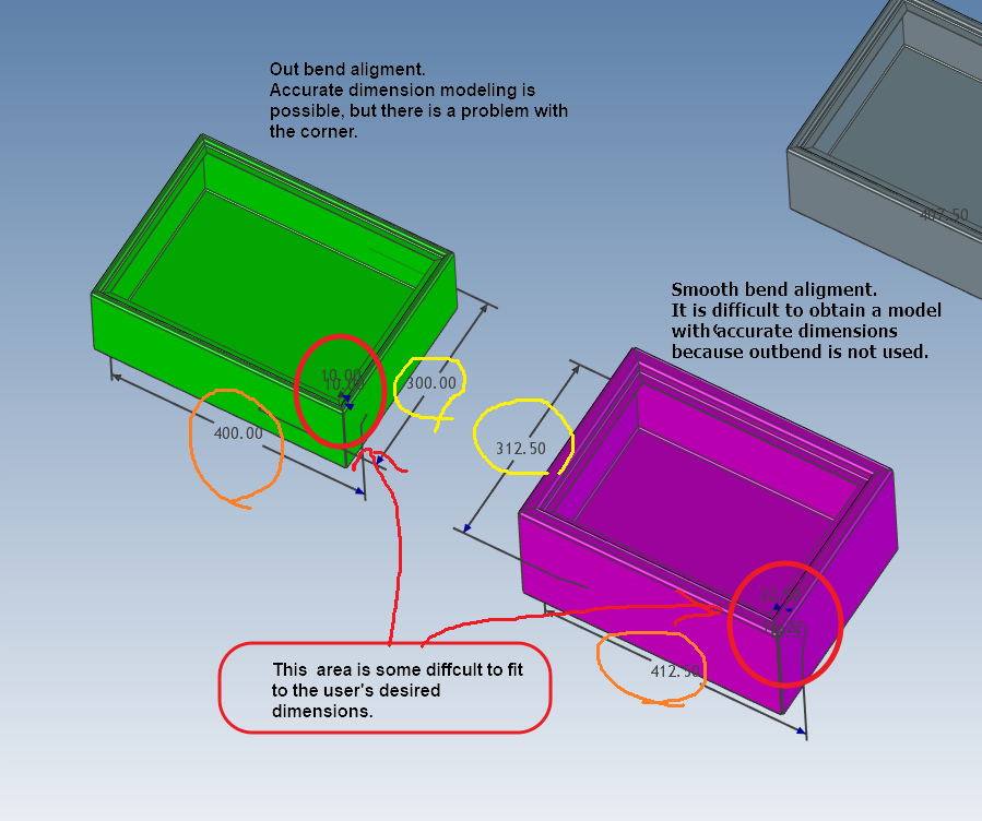
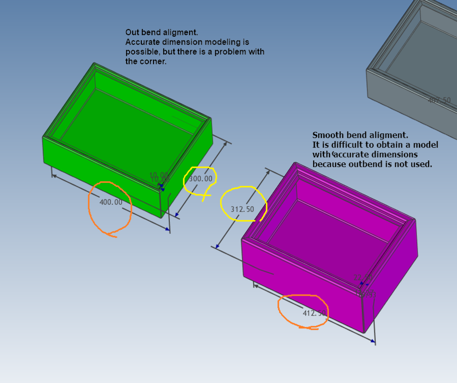
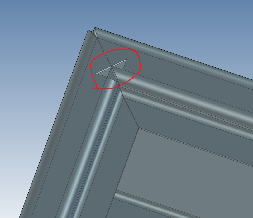
Hi. Joseph. Thank you for spending so much of your precious time. There is no big problem if the externally large dimension is reduced as much as it is increased. However, in the case of modeling in the red circle, it is inconvenient for the user to do the work by reducing the increased amount after calculating it when modeling. Thank you very much. Joseph. ^^

-
There is no problem with the shape, but it is difficult to make a model with accurate dimensions. Sheet Metal Part51.ics
-
Thank you very much. Josep. But, I cannot get the box to the dimensions I want using the smooth bend alignment option. I would like to design an exact box using the outbend option.
-
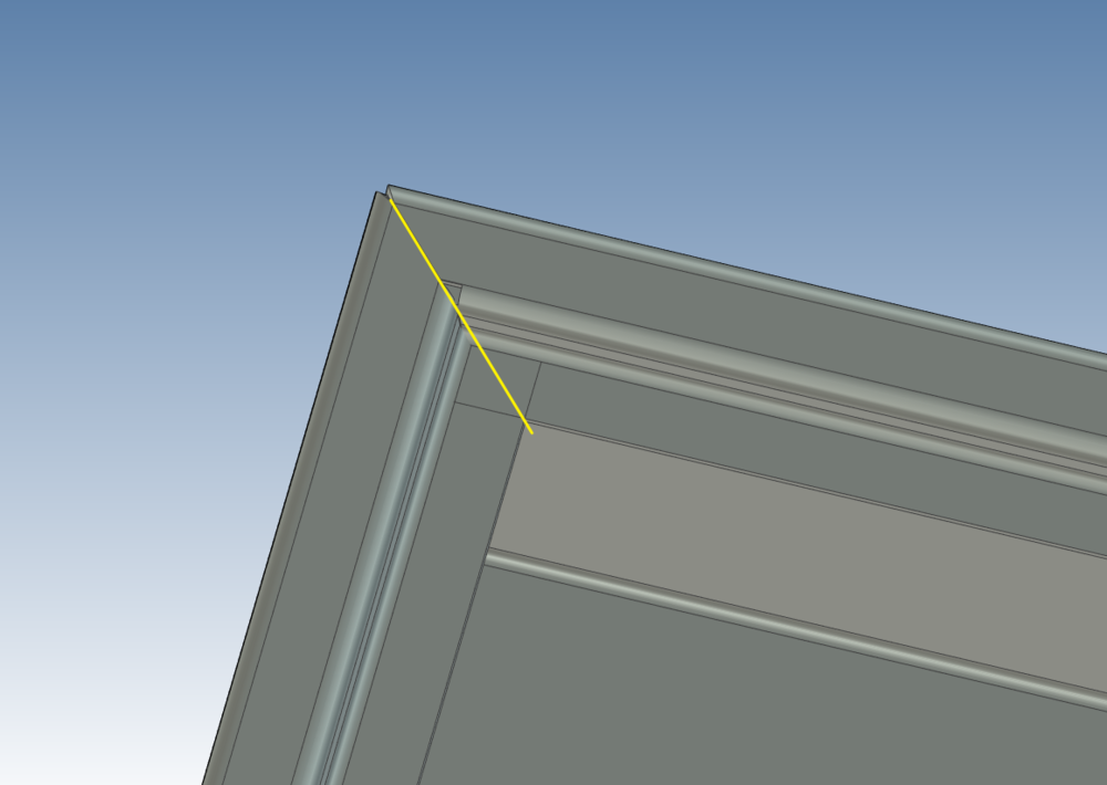
Hi. I have a one more questions. In this case, how can it cut out the model like the yellow line? Thanks. Sheet Metal Part54.ics
-
Thank you very much. jolizon ^^
-
Thank you very much. Kevin. for answering my questions. ^^
-
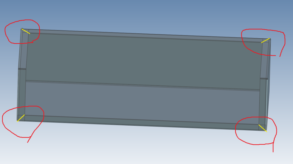
Hi I would like to make a miter like a yellow line on the sheet metal model as shown in the picture. I've tried several things, but it doesn't work like I thought. Which method would you like to use? Thanks. Sheet_Metal_Test.ics
-
Placing a feature at the origin of the coordinate system..
tgjang replied to tgjang's topic in Tips and Tricks
Thank you. Malcolm and Johas. There's something wrong with my computer. ^^ Ctr+LMB.mp4 -
Placing a feature at the origin of the coordinate system..
tgjang replied to tgjang's topic in Tips and Tricks
Thank you Malcolm. In structured mode, an empty scene automatically goes to the world origin. In innovate mode, the feature is placed where the mouse cursor is placed. ^^ -
Hi. It is very convenient to place the first feature at the center of the Absolute Coordinate (0,0,0) when starting the design work. At this time, press and hold the Ctrl key and drag it to the screen, and the feature enters the Coordinate center exactly. Drag_Feature.mp4
-
Cary. Thank you very much for your quick response. I think it's a validation issue with the wireless internet. I downloaded it from the external and wired computer and installed it. I am also glad to hear that the CAXA View direction problem has been resolved in the IronCAD 2023 Version. Thanks.
-
Hi. I tried to install IronCAD 2023 after deinstall IronCAD 2022, but failed when an error message dialog like the attached photo popped up. How can I install IronCAD 2023? Thanks.