


PWATSON
-
Posts
163 -
Joined
-
Last visited
Content Type
Profiles
Forums
Blogs
Downloads
Articles
Gallery
Posts posted by PWATSON
-
-
Malcolm,
That really works well too. I so rarely ever change the selection filter that it never occurs to me to use it for things like this.
Thanks for the tip.
Peter
-
Ah!
I just found it...
use the eye dropper and right click when applying..gives a dialog to apply to one surface only..
-
Hi ironcad community
I have a custom tank I created from 304 stainless sheet.
I want to apply a color to only the outside surface of the tank but cant seem to figure it out..
Does anyone know how to do this?
Thanks
-
Thanks Malcolm,
I will try the parallel lines command..It may be easier because you can just enter a length after invoking the command..
The offset command works fine it just bugs me that i have to always go to the instance menu with the mouse to enter the offset value..I like that the parallel lines command prompts for a keyboard entry for the offset value.
It never ceases to amaze me at how some seemingly insignificant things can annoy me so much..i must be turning into a cranky old guy

-
Thanks Malcom,
Do you know if there is an easy way to access the menu options without having to use the mouse..
The big one for me that always bugs me is when offsetting. The offset value or distance is buried in the instance menu and every time i offset i need to go down and enter into the menu...
coming from autocad, situations like that, the default keyboard entry is the offset value which makes the command so much easier to use.
-
Thankyou Malcolm..
That is awesome..That is exactly How AutoCAD handles sub styles. I cant believe i never figured this out. Ive been running this program for years now and i have been using two independent styles depending on the geometry...
Finally i can have one style to suit all.
Peter
-
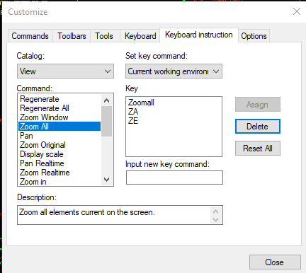
I just added ZA to the custom keyboard instructions...
takes a millisecond to type ZA
(i also added ZE from those retro ACAD days when it was zoom extents)
Works like a charm.
Peter.
-
 1
1
-
-
HI,
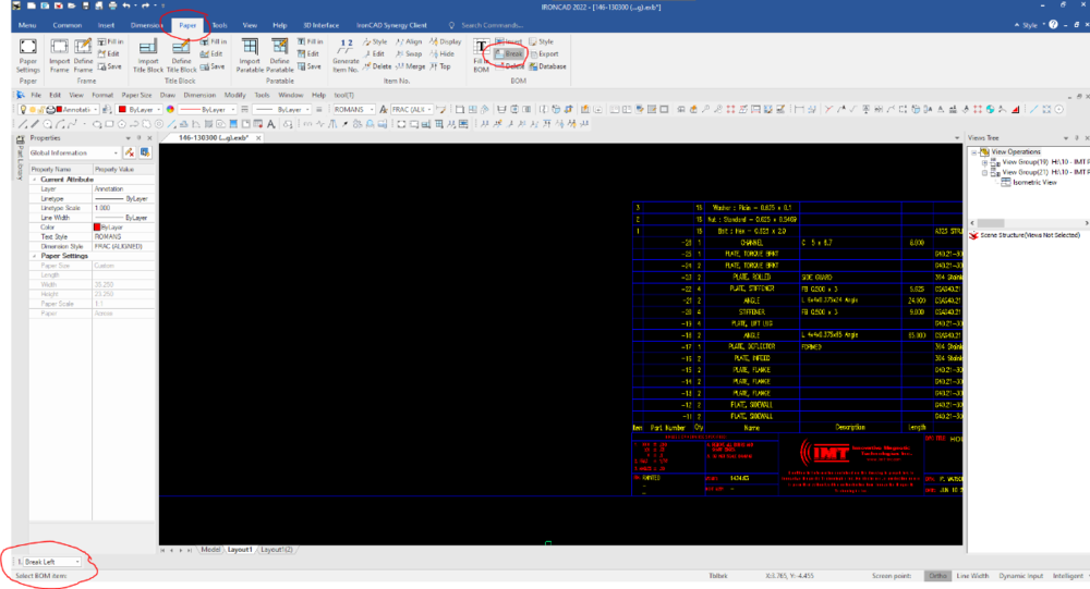
Under the paper tab on the ribbon there is a tool in the bom section that allows you to break the bom table.
When you select the tool there are three options that you have.
Break left
Break right
Set break point.
Set break point allows you to pick a location for the split bom to move to. ( in your example above that was the bottom left hand corner of the existing b.o.m.
Then you choose break left or right depending on the direction you are splitting, and then select a line on your b.o.m where the split is to occur.
hope that helps.
Peter
-
 2
2
-
-
Cary
That was simple as hell
 ...
...
I really made it way harder than it needed to be.
Thankyou
-
1
-
-
Thanks Kevin...
How would i do that and be able to modify the diameter and thickness upon dropping it in...Or do i have to make one for each size i want to use, which quite frankly could be hundreds of variations

would that be using parameters and design variations - both which I am quite unfamiliar with using.
-
I have created some custom stock sheet metal sizes for heavy plate that we use regularly. 1/4" thru 1 1/4" plate. I realize these technically are not sheet metal however I have done this because of the functionality of creating DXF files from Iron cad mechanical where I can have the dxf file populated with the material name, file name ect for sheetmetal parts.
My question - Is there an option to drop in a round piece of stock? Every time I want to make circular plate I have to drop in a square sheet and then sketch a circle on it.
-
Fantastic. Lets get this fixed. I have been struggling with this for a while too but i never connected the dot that it was after using CAXA.
Peter
-
1
-
-
Im having the same issue..
Any response on this thread, Hotfix or update.
Peter
-
Ah, very handy..
Thanks Malcolm
-
Thanks Dariusz
I appreciate the help.
cheers
Peter
-
That's a great tip for scaling the templates..
Thanks.
Now Im going to go and modify all my templates

Cheers
Peter
-
Hi Everyone.
This is a technique i use when dimensioning in CAXA which saves me quite a bit of time. I figured i would post in case there are some out there who are not aware of CAXA's strength when dimensioning drawings.
It is possible to make changes to your dimensions at the time of placing the dimension rather than placing the dimension and then going back to edit. In order to do this, a right mouse click is done when placing the dimension. This will open the dimension properties dialog box which will give you options to change the style, add notes, add prefixes and suffixes, tolerances ect before the dimension is placed onto the drawing.
I created this short video to show the technique.
If this is new to anyone I hope it helps.
Cheers
Peter
-
Thanks Maurizio,
I gave that a try but not sure if I can make it work..
It seems the file has a part numbering "rule' based on the parameters of the fastener (codexLxM).
If i could somehow manipulate the parameters I may be able to make it work but not sure where these parameters are defined.
Peter
-
We are implementing a new manufacturing software system and part of this implementation is that all of the fasteners we use get part numbers.
I have the IC mechanical addon and with the fastener tool it brings in a part number.
I was wondering if anyone knows of a way I can modify the part number that IC attaches to the fastener when i drop it into my scene. Maybe a data file i can modify.
Currently i end up having to manually change each fastener part number as i drop them in..
Thanks
Peter
-
Tom
That is a great question and one I am hopeful someone smarter than I can answer.
I suspect its because Caxa is a 2D drafting program modified for 3D environment. In 2D drafting the paper space model space way of drawing works brilliantly and probably is the simplest way to depict multiple scaled views on one drawing. In a simple part drawing where there is only one scale then viewports aren't necessarily required and for 3D where the program does the scaling work for you view port drawing isn't needed.
The 2nd thing is that unlike ICD if you want multiple sheets you need to use the Layout tabs.
This unfortunately suffers the same problems as I described in my video, where if the B.O.M is not present on the same layout as your views you cant Itemize anything.
..Yet i still like CAXA. I really haven't used the ICD interface much so am really not even that familiar with any of it's idiosyncrasies. I bailed on ICD almost immediately as i tried to set up our company template file.
Cheers
-
Hi Tom,
attached is a video i made of what i was trying to explain..
It would be interesting to get Roberts Take on this as I may be off in Left field here and just missing something.
I really like Caxa Draft but it has some very quirky parts which make me want to toss the whole computer out the window some days..

Cheers
-
Hi Tom..
That is a great video of how to use view ports and is exactly how view ports should be used and the way that Autocadd operates as well.
The only thing is you'll notice there was never a B.O.M. imported or any annotations added such as section views or details.
I suspect, from my experience, that is because CAXA Cant seem to handle having the B.O.M on the layout while the 3d views are in model space.
As well, you cannot create sections on layout space for items that are in model space. In order to create sections, you have to first create the sections in model space, but the caveat is that for the section annotation to be displayed properly when you go back to layout you must know what scale the viewport is at and then scale your annotations appropriately.
It really is a messy way to draw.
However, if you just pick a space...model or paper and drop your 3d views there and use the scaling function of the view creation dialog (ie set your scale at view placement) just like in ICD then let CAXA deal with the dimensions it all works nicely.
cheers
Peter
-
I used autocadd 100% prior to adding Ironcad to the mix and still use it alot. For Me the similarities of Caxa and it's ability to seamlessly open autocad files was an obvious choice.
Here are my $.02.
In Autocadd I always use model space for 2d layouts all drawn at 1:1. I then utilize paper space to do my scaling and dimensioning and annotating ect.
Using CAXA draft this way when working with 3D doesn't work..(at least as far as i can tell) as the program is unable to place 3d views in model space and then have the paper and BOM in paper space (also known as Layout space). You cant itemize anything.
So for 3D caxa use I put everything in one space (for me paper space) and let Caxa take care of the scaling ect. This way there is only one dimension style, text size ect to deal with.
Essentially I use CAXA in the same manner as ICD
The only time i use Model space is to import some reference geometry ect.
I really don't feel there is a huge difference in the way the two programs Operate. There are some definite pluses to ICD when it comes to ease of view manipulation compared to Caxa and Caxa does some really weird things with View labels and ordinate dimensions ect, however I find there is much more flexibility in Caxa....sort of iphone vs samsung

cheers,
Peter
-
Thanks Jonas..
I just got back from some time off and read your post.
I saw the numbering function in IC Mechanical but really didn't know how to use it. I will watch the video and hopefully that will help.
Thanks, Again.

question about exporting a model
in General Discussion
Posted
Hi All,
I searched around the forum thinking i had read something about this topic but couldn't find one.
I have a model of an assembly which I would like to send to a customer for reference. I want to send this model as a dumb block.
I have used the shrink wrap command to create the simple version of the model and it does a good job at creating a single part for the entire model assembly but this model is an Ironcad .ics file which my customer cannot use.
When I Export this file as a step file it converts the model back to an assembly full of parts that can be turned on or off and manipulated. Granted these parts are all breps but it still provides the end user the ability to turn on or off and copy parts and also the ability to see how the unit was fabricated ect.
Is there a method to export the simplified block so it remains a simplified block?
Thanks.
Peter