


tcooksey
-
Posts
169 -
Joined
-
Last visited
Content Type
Profiles
Forums
Blogs
Downloads
Articles
Gallery
Posts posted by tcooksey
-
-
-
-
Has the Rhino Integration been discontinued in IC 2018?
I did not see the option to select it during installation.
Troy
-
Hi Tito,
1 of our customers having the same issue with the same printer.
When they add images it will work because the export to WRL also create the images. But i won't pick up the color. Custommer told me they looked at it with the dealer of the 3D printer and they said ironcad isn't creating the bitmaps for the color.
So i asked him to test if he only ad images and no collors. example, a image of the collor red etc.
i'm not sure or we export it wrongly or they import it wrongly. or mayb is there an easy way to solve this?
As a follow up, we finally got this to work with Photoshop ( neither IC or Rhino worked, and I have not had a chance to try it in SW ).
See the best practices document I attached previously.
Our workflow was;
1) import OBJ data into Rhino
2) add base color of meshes in Rhino by assigning material colors
3) Export as 3ds out of Rhino
4) Open 3ds in Photoshop ( most recent version being used )
5) Generate UVs
6) Open image map in PS and copy paste onto 3ds file
7) Once in proper place MERGE DOWN image map
8) Unify for 3D printing
9) Generate UVs
10) Export VRML with image output as BMP format 24bit.
Most of this is in the Best Practices document, but it assumes you know how to work with the 3D files in PS.
You may need to watch some demos on You Tube as we did.
Just a note to Tito and IC, it seems like BMP image format works best with that 3D printer for the VRML output, which is current not an export option in IC.
Troy
-
Thanks!
FYI, I have attached a document that the Rapid Prototype vendor sent me regarding how to generate the necessary files in several different software packages.
Note I also tried it in Rhino and this did not produce proper results either ( did not maintain image map ).
Troy
Best_Practice___Stratasys_J750_Color_Selection___English_A4_Print__002_.pdf
-
Hello Troy,
Please send us the original .ics files associated with this error so that we can conduct an initial investigation of the issue. Once we have done this, we will be able to determine if there is a way to get around this problem or if it needs to be sent to R&D to be resolved.
Tito
Tito,
Thanks.
File attached here.
Note there is a mesh and a solid model of the figure in the file, but they seem to work the same during export.
Troy
-
There is a new rapid prototyping machine from Strataysys, the J 750.
This machine is a Polyjet / Objet machine capable of color 3D printing.
They boast 330,000 possible colors as it mixes RGB resins as it is building the part.
The parts they show are simply amazing.
The machine supports images and textures mapped onto the objects and builds a 1 mm thick layer of these colors as an outer skin.
The input they require to use on this machine is a VRML file.
Attached is an image of a figure I am trying to export in this format ( on the left ).
The figure on the right is the re-import of the VRML file I exported from Iron Cad.
This file was exported saving the image map in jpeg format.
It is obvious that the jpeg image does not support the alpha transparency of the original png file I mapped on, but it is also box mapping the image on the object.
I had used slide projector mode to map the image originally.
If I set the export options to gif, the VRML file imports the geometry fine, but no image map.
My first choice had been png as it supports transparency in the alpha channel, but the program crashes during export ( report attached ).
Any thoughts about this issue or how to get proper results?
Thanks,
Troy

-
Hi Troy,
It is because your scene browser is "floating" and not docked to the side. Have a look at this video.
(Camtasia recording, if needed download CamPlay here: http://goo.gl/kZ6Pua )
Jonas,
Sorry I have not been on the site for a few weeks to see your response.
You are correct, my browser looked like it was docked, but indeed was not.
Docking it did remove that notation.
Thanks a lot for your insight.
Troy
-
-
Can someone remind me what it means when the IC file name in the windows tabs appears as
FILENAME.ics:1 instead of FILENAME.ics
I recall this happening before, but can't remember why.
When this showed up yesterday, my scroll wheel zoom stopped working when you are in a 2D sketch.
Thanks,
Troy
-
Some input.
I have some customers working similar to Troy, the only difference is I tell them instead of making copies ( -1, -2, 3 etc..) I have them make backups ( -BU1, -BU2 etc.) And continue to work on the original file. What this does is allow any external links and drawings assocaitivity to be maintained better.
tom
Yes that is a good idea.
We have had issues using linked parts from a master catalog ( getting accidentally changed or deleted ) and have not been able to use external links as effectively as we might.
Thanks Tom, always a wealth of good ideas!
Troy
-
I am starting a two person project where we will both be adding models to a main assembly on a network drive and want to avoid overwriting each others changes by accident.
The question is, has anyone ever used IronCad in a collaborative setting where more than one person is contributing to the model? If so how did you manage the models?
I have three seats of IC and we keep all of our project files on a shared network drive where any of us can work on the shared files at any time.
We typically do not make the files Read Only, as I might want to finish or rework a file that one of my employees started.
We usually save multiple files as we progress through a project;
PROJECT X-01.ics
PROJECT X-02.ics
PROJECT X-03.ics
Usually doing a SAVE AS, when we do a major design change, or if it has had several days of work.
If a file becomes corrupted or lost we don't lose too much, or we restore it from Carbonite.
I suppose you could have a READ ONLY folder and post files to there when you think you are finished.
You can always start a new file of revisions from that read only file, PROJECT X-04.ics, and save your own work to your own folder, then file it to your read only folder when you are done.
I think if you are just careful, and save multiple files as you go along, you should minimize any accidents.
Cloud backup and automatic drive backup also help minimize accidental deletion.
Good organization of your files is also a plus.
Does this help?
Troy
-
Just noticed the materials catalog that can drag and drop color, material name, density all in one whack.
Very nice!
So here is what I would like to do along the same lines.
I have created a massive catalog of drag and drop colors based on a popular color matching system.
I would like to be able to drop these colors on a part and not only have it change the color but also add a custom property called Color and assign a color name to that property, for example PMS 750 C.
Is there a way to modify my current catalog to do this, or recreate it to add the additional info?
If this is possible, would the variable have to be assigned to the part prior to color drop or could the drop add it on the fly if not already in the part info?
Thanks,
Troy
-
So the Compose facet model just contains information that relates it to a catalog and element there in, and just does a swap when you convert it?
If that is correct, does the catalog need to be opened when you convert it, or does it just go out and find it in your default catalog folder?
Troy
-
Okay, that worked.
Just out of curiosity, why does it need to pass through a catalog?
I am trying to work out a work flow to streamline design changes down stream from some of our manufacturing vendors.
As I have mentioned previously we do some Lego like toy construction sets.
We currently have a part database consisting of hundreds of parts.
Ultimately I am going to put the parts in several IC catalogs so that we can drag and drop our build designs, but that is in progress and we have just been doing it by copying files into the assembly we are building ( not externally linked to the database as we are still making changes to the database ).
What I would ultimately like to do is send the vendor ( or actually my clients Hong Kong office ) my native ics file, let them open it in Compose and make various part substitutions by dragging and dropping parts from the Iron Cad catalogs I create from our database.
Send the Compose file back to me and then I can use that going forward if I can convert it back to IC solids.
Currently I have to work from photographs of the changes and go in and update my original IC file.
So far so good in terms of how you guys set up the system for converting the compose meshes to solids ( which is functionality I need as we go forward with additional downstream uses ).
My problem would be that we have already built a lot of sets that just have minor changes to turn them in to a new or refreshed product, so I don't want to have and rebuild a 500 piece set just to be able to convert the Compose model back to IC.
Do you have any suggestion of how to work around this?
Do I just drop that whole assembly into a catalog and pull it back out and start with that for a new item?
Thanks,
Troy
-
This functionality only works with pats in a Catalog that are already solid.
So the sequence goes like this:
1. Save solid parts from IronCAD into a Catalog.
2. Open that Catalog in Compose and make an assembly.
3. Open that assembly in IronCAD and the Catalog then you should be able to convert them back to solids.
Kevin,
Thanks, I will give that a try.
Troy
-
The new functionality to convert a Compose model back to IC solid is extremely cool.
The problem I am having is with older models.
As a test, I open those in IC2014
Save As a new file
I open the newly saved model in Compose 2014
Save it as an .ic3d file
Open this back up in IC2014 and try to convert it, but it does nothing.
Is there something different I need to do or is this something that is being fixed?
Thanks,
Troy
-
Does anyone else need to import Illustrator (or other vector) artwork into IronCAD 2D drawings? I've never been able to figure out how to go directly from Illustrator to IronCAD, so we have been using Freehand (version 9, back when Macromedia owned it.) We would create a new Freehand OLE object in a drawing, which would open up a Freehand window, allow us to copy the Illustrator art into the Freehand window & "Exit & return to ..." from the Freehand menu. Works great - gives us access to all sorts of artwork that can then be scaled in IronCAD without any pixelization. Plus, we could then open the file from IronCAD for editing, based on the needs of our drawing. Then we could drag the art into a catalog for future uses.
Now we're updating our computers & Freehand won't load on the new systems. Adobe bought Freehand a few years back & doesn't intend to update it (i.e. they want it to die.) So now we find ourselves with IronCAD 2D catalogs full of Freehand illustrations, which we can drag onto a drawing sheet, but won't be able to edit - and no way to get new artwork, save making jpegs (which is going to be another issue, when we can't get Microsoft Photo Editor to work with newer operating systems.)
Mike,
Here is the technique I use to do that:
Convert the vector .ai to dwg format.
Start a new ics file.
CREATE>2D SHAPE
Orient this drawing plane at 0,0,0 so that you are looking down on the plane from a top view ( this is critical )
Edit this 2D shape
Right click on the drawing grid
Select Import and select your dwg file
When the line work imports in, select all of it and copy
Create an Iron Cad drawing
Then hit paste
The line work should appear as an object that you can move to the location you want.
Note if it is really complex, it might be very sluggish to move.
Note in the ICD drawing, you can create a new drawing catalog and drop this logo in there for future use.
We typically have a need to covert Illustrator art to 3D parts in Iron Cad.
We typically import the .ai file into Rhino and process it there.
Usually .ai vector art is pretty sloppy and spiney when it comes to using it in Iron Cad.
You usually need to eliminate duplicates and extra lines created from outlined lines that Illustrator often creates.
We usually convert the line work to arcs ( Rhino function ) which converts splines to arcs and straight lines.
Do a test solid extrusion of you outline to make sure the curve does not self intersect.
Explode the curves before exporting as dwg as the Rhino exporter will export poly-curves as splines, and these typically are not editable in Iron Cad.
Troy
Any ideas?
-
Tom,
I have a good hand model that started life as a mesh model but was converted to a surface model via Rhino T-Splines plugin.
To pose fingers you would need T Splines.
Would this work for you?
Troy
-
Tom,
Not sure if you are looking for a plastic helical compression spring in plastic, or a cylindrical compression spring.
The latter is available at centuryspring.com.
This is a great supplier for off the shelf stock springs.
Troy
-
I have a model that is giving me incredible fits...
The problem showed up as I was attempting to export in STEP format. The exported model would not import, except as a rather torn up surface model. Importing into Rhino revealed numerous "problem surfaces." Repairing manually in Rhino has proven *EXTREMELY* tedious and time consuming (partly due to my limited Rhino skills, I'm sure).
But here's the deal. I have attempted to start over with the model, periodically exporting and re-importing to check model validity along the way, and it just always seems to blow up. In the past I have often "frozen" my models by exporting to .x_t or to .sat, then re-import. I did this to ensure that some smart feature didn't get out of order and ball up the works, and it always has seemed to work for me. This model, however just fails the acid test very early on in its development.
It seems that perhaps the problem is a result of my fairly extensive use of variable-radius blends, but I don't know...
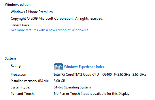
Now I'm beginning to wonder if I don't have some kind of CPU bug -- like my machine is failing at edge trimming calculations or something. It doesn't seem to matter whether I'm using the Acis or Parasolid kernel, but I can't say I've done extensive testing in both.
Is it possible that I need a new machine? Are the latest processors better at this stuff? Seems far fetched, but you never know... I know that a few years ago I had a model that would not regenerate, but when I put it on another PC, everything worked fine. Weird, but true.
Or are there cumulative rounding errors going on that I can fix with a setting somewhere. Is there a setting for IronCAD's internal precision? Would it help if I modeled it at 10X scale, then scaled it down at the end?
Scratching for answers.

Eric,
I had recently reported some problems I had with the step format.
Models were similar to what you described ( torn up ) when imported into other packages such as Wildfire.
Parts will be missing in the step file.
This occurs when you have linked parts across different non linked assemblies.
The first assembly it comes to will have the parts, but occurrences thereafter do not.
So I am not sure that you can blame your machine.
Seems like a problem with the Step translator or ICs integration with it.
Troy
-
In the Whats New in Ironcad 2013, I followed the video clip for the 2D Text in Sketch feature, and found that the text would not extrude as shown.
I did find that if the text was converted to curves, using the break up command (right mouse button menu), it did then extrude, but you lose the ability to edit the text. Is this a bug or intended?
Also, the text height value does not seem to correspond to the overall height of the text characters, for example, a capital "I" is not 10mm high when 10 is entered when using metric units.
Has anyone else found any issues when using this new feature please?
Karen,
There are a few buggy things about this feature, but it actually works pretty well if you work around the issues.
Often when the CAPS lock is on, some letters will not appear in the text field when you type.
Turn off the CAPS LOCK and use the shift key to get capital letters.
If you are changing text, pick at the end of the text and back space to delete.
I have reported these issues previously.
Troy
-
Hi Guys,
Something to the side of Blender. Check this out if you haven't: http://www.rab3d.com/index.php. He has done things with blender and created some tutorials.
Regards.
Thanks,
Will check it out.
-
Troy, I am in the process of evaluating Blender becuase I need to model things lately like splashes, smoke, and dripping effects which Blender can do and very easily once you understand particles.
The rendering in Blender is phenominal once you understand ( like anything). The nice thing is realtime render ( render cycles) and you can get nice quality renderings fast with minimal setup. I want to get GREAT renders which require the use of NODES which is an entirely new world for me. But theres a ton of videos on youtube which makes learning much easier. After playing with it for about a month and watching a boatload of videos, I still need more learing but I feel once I get it Blender will do ANYTHING you need it to do, its truly an amzing rendering and animation tool!!!!
Atatched is a video of an Ocean animation, it was created with about 5 clicks and then took 24 hours to render and create animation, amazing.
Tom,
Sorry for late response as I have been out of town.
Wow.
That looks great.
Have you done any modeling in IC that you have passed to Blender for rendering?
Troy

Rhino Integration
in Tips and Tricks
Posted
Is that on the horizon?