
dleczynski
-
Posts
2,751 -
Joined
-
Last visited
Content Type
Profiles
Forums
Blogs
Downloads
Articles
Gallery
Everything posted by dleczynski
-
This is very problematic, I used to indicate with an error message if you export to DWG your dimensions are not connected to the view - but this view may be updated.
-
you just need to change the model on the PARASOLID kernel and working correctly, there is some error in the ACIS. also works in the ICD
-
not available
-
Hi SVAN GELDERN, Try free designspark. stp imports exports to PDF 3D. The effect is very good - I was surprised at the quality. fc_al_s_103.pdf
-
model 2 in this model is the problem: you have to share the curves and give another relations that the model was consistent. If you do not see the outline of the extrude and you need to edit the profile again. You can not change the auxiliary curves construction or disconnected because the whole outline is skipped, so remove it. This method is not practical because you lose your connection. At the 10:05 minute movie bug
-
model 1 I try to do this simple mode, but in a parametric way. Often in such models curves arise in one sketch. It is easier to determine the relationship / bond between the curves. If you do offset curves and trim. You can add a dimension offset. Extrude also doing the problem, does not preserve the dimensions. Do you have any idea? So it looks like the inventor: Selecting outline works only in the structural parts, but does not select the line of cut as INV: I want to see how to build the model. if you want to add dimension to the offset, you need to hold down the SHIFT key and then add a lot of bonds: tangent, concentric, conform to gemetria worked.
-

Problem exporting *.icd drawings to dxf and dwg
dleczynski replied to HDEAR's topic in General Discussion
first save the file, then export -
I checked on multiple computers - it works.
-
simply try to delete the two entries in the registry. HKEY_USERS\S-1-5-21-2134629734-1534462894-3128833934-1000\Software\Microsoft\Windows\CurrentVersion\Explorer\FileExts\.ics HKEY_USERS\S-1-5-21-2134629734-1534462894-3128833934-1000\Software\Microsoft\Windows\CurrentVersion\Explorer\RecentDocs\.ics right click ikon - set as deflaut ironcad enjoy.
-
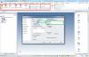
Example: Path to paste default file SysSetting.xml and replace and : C:\Program Files\IronCAD\2015\bin\CAXADraft\Config\pl-pl After swapping the file to remove all folders: C:\Users\%USERNAME%\AppData\Local\CAXA C:\Users\%USERNAME%\AppData\Roaming\CAXA IRONCAD run in the general options to change the default format. As standard there is no such option. In the video here shows what needs to be done after removing and swapping files. enjoy. SysSetting.zip
-
try this: http://www.ironcad.pl/forum/viewtopic.php?f=69&t=18
-
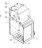
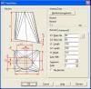
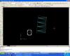
in the Annex model inventor, 2010. You can expand it in IronCAD. Inventor automatically approximates an ellipse into a set of 4x8 sections. In IRONCAD approximations can be done by exporting DXF R12. I still have a problem with the creation of the model. In addition, Inventor approximation bows and distorts them. ko__322_nierz.rar ko__322_nierz_opis.pdf
-
Almost done, because I think I get a whole without any problem. He had one more experience with an ellipse? Lines to show and explain, but in the wrong place. asa.ics
-
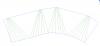
AutoCAD developed this sheet without any problem. If the same way you do in a square or circle will be a line.
-
so I know that I can, but there is no line bending / annotation bending line.
-
How to do it in IRONCAD?
-
How to I delete relations on structured parts?
dleczynski replied to tlehnhaeuser's topic in General Discussion
very helpful, too long ago I asked about it Rules the structural part. -
I wanted to ask how to organize files suggests IRONCAD. To not become confused and easily create documents and statements BOM.
-
tip 3d_curve_tip.zip
-
Lack of this feature in the new 2015. What changes are to be in the sheet metal in 2015?
-
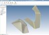
Joe, The surface elements can "well" - "only" in part structural design. Between the curves add up relations (constraints). Can edit the item and other shapes will be followed. See my example:
-
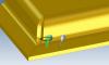
I want to create a separate metal parts. Add automatically closing 45 degrees. If you have one part of an operation to generate the correct results. If two different it is not. How to change the orientation of the final machining allowance? I noticed that it is turned
-
How to do? or why the same settings will produce different models BUG_SHEEET_METAL.ics
-
how to add cross-section isometric view?
dleczynski replied to dleczynski's topic in General Discussion
You can not add center marks and other annotations. Rotation angle conforms to the orientation or not help. -
how to add cross-section isometric view?