


bmckelvie
-
Posts
148 -
Joined
-
Last visited
Content Type
Profiles
Forums
Blogs
Downloads
Articles
Gallery
Posts posted by bmckelvie
-
-
That is really handy, i spend a lot of time making custom 1:1 dxf's for profile cutting and that tool would really simplify the process.
-
My work flow is a lot like Mikes,
I supply the fabricator with a drawing that has two parts on it. The first is the flat pattern that they can use for their profile cut. This view has only the overall dimensions on it.
The second is the finished part with all dimensions I care about on it. I always have a note on the drawing saying to make the part to the finished dimensions and the flat pattern is only for reference.
I use the default K factors and have had good luck.
As Mike says the fabricator knows his equipment and has the experience of actually making the parts.
Some fabricators prefer two drawings with the first one having only the profile part at 1:1 scale
Brent
-
Thanks that we really useful,
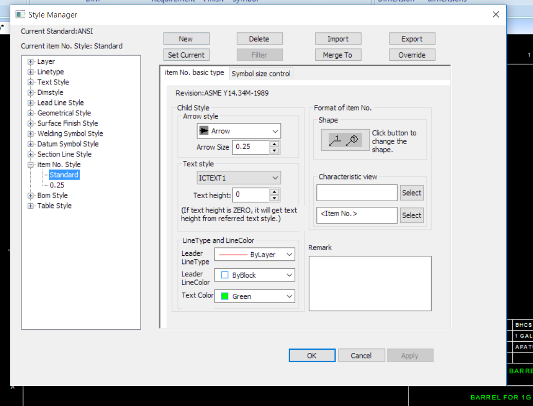
The problem was that the characteristic view was set to part no not item no by default and that had no number associated with it.
-
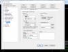
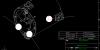
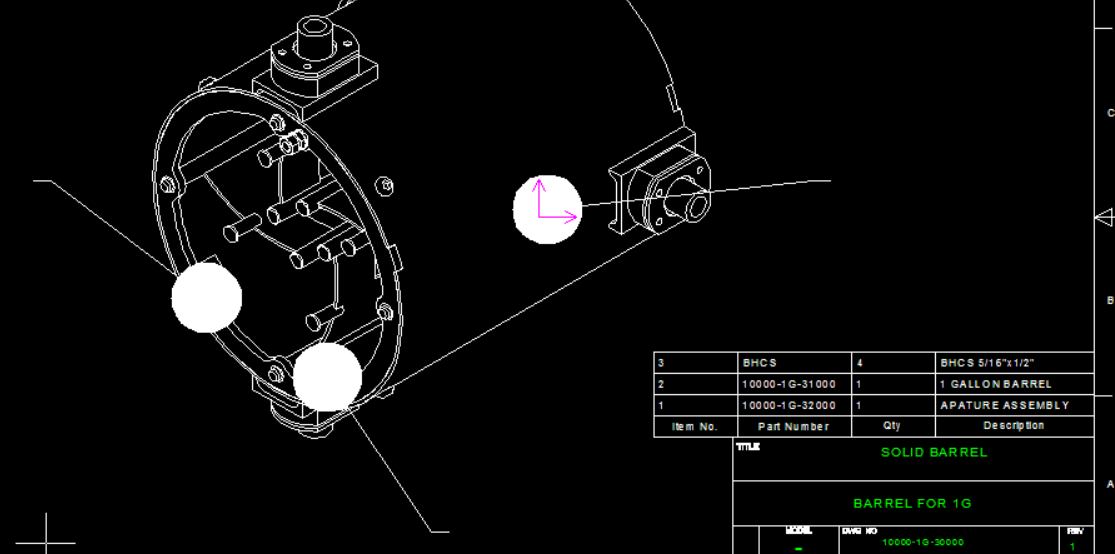
After much fighting I am slowly and frustratingly transitioning to Caxa from ICDRAW. I have my bom table but I can not get Item bubbles !?, how are you supposed to make them?
I'm attaching a screen shot of what I get when i try to auto generate them. it appears to be making them backwards, filling in the balloon with solid colour and not giving any item number.
Thanks
Brent
-
Thanks, your instructions are well done and helpful, but unfortunately they left me with the exact same problem I had before.
I did finally figured out that the names in the 3d model (User Name, Description, and Part Number) do not relate to the same names in attributes. the attribute names that I had to use were Name, Remark, and Drawing No.) I have no idea how you are supposed to know this, especially as IronCads own video on the subject uses different names for them. I found them by going through Caxa/tools/options/system/matching rules and reading all of the preset matching rules and guessing what they actually did.
The only problem I have left with the matching is any custom property I add will not show up, even after setting it in 3d properties, adding it as an attribute in the template, and adding the matching rule in Caxa options.
-
I am having a really hard time getting the CAXA title blocks to autofill.
I followed this video
except instead of making a new title block I am just adding a few new tags to the existing default title block. (The part properties User name, Drawing Number, and Description specifically)
The problem is only the drawing number will show up everything else does not work.
Any Ideas on how to make it work?
-
Thanks a lot everyone, that really helpful, I was constantly clicking on the wrong (the thin one) edge and getting errors.
-
I have been trying to make a mitered sheet metal part in IronCad and can not figure out how to use the feature, I have also been unable to find any documentation on it ether so I figure others probably are having the same problem. does anyone have a video or a tutorial showing how?
Thanks
Brent
-
I have been an IronCad user for about 5 years and continue to be with my own projects, but I recently started at a new job where I have to use Solidworks for modeling, and in the last two weeks I have started writing down my thoughts whenever I get annoyed with IC or SW.
This is what I have come up with, and remember that it is my opinion so it probably contains many inaccuracies, but I think it is a fair look at both (with a little emotion thrown in).
Modeling – IronCad wins hands down, no comparison. It is faster, more intuitive, and just nicer to work with. My only complaint about IronCad's modeling is I wish I could make planes there are some times while modeling or aligning parts that a plane would just make everything easier. (I know structured parts have them but I find that structured parts feel like an after thought and are way to limiting for anything serious)
The big advantages that IronCad hasl are:
The catalog combined with Drag and drop modeling, Making parts/assembly throwing them in the catalog and pulling them back out at will is great.
Boolean features – nothing needs to be said, they are perfect
TriBall - All of the fun ways I can move, copy, pattern, and rotate features and parts works great.
Sectioning 3d models - to get a better view of the inside is very handy and works well in IronCad
Face Editing – I create a lot of metal structures to be welded together, and making angles on the ends of tubes through face editing is great. (a good enhancement would be to allow resizing the length after a face edit!)
Assembly’s – IronCad wins again, I love how IronCad deals with assemblies, being able to make new assemblies from inside a scene and opening them separately is great.. I find Solidworks assemblies to be limiting, slow and prone to exploding in horrible ways. The only thing that I like about solid works assemblies are when I click on a part it has all of its constraints listed under the part in the tree as well as at the bottom under mates (constraints)
Creating Detailed drawings – Solidworks wins here, It automatically adjusts line lengths for hidden lines so they actually look hidden, its hole call out tool is wonderful, moving dimensions from one view to another is effortless and linking the notes to drawings properties is quick and intuitive. It also deals with large changes to the 3d model better. IE: when the model changes solid works finds the correct edge to reattach to very nicely. Solidworks BOM and dimension snaps work better and alining them to a shape outside the view is much easier. Basically it works with you instead of fighting you every step of the way. IronCad has CAXA now and things are improving but so far I still find it quite awkward to use.
Mechanism mode- Solidworks wins big here because it actually works. After using Solidworks for only 3 weeks I feel confident in saying that IronCad's mechanism mode is broken and incomplete. I don't think I can describe how much more intuitive and easier to use Solidworks mechanism mode, and constraint solving is. This is my single biggest complaint about IronCad.
Sheet Metal – IronCad wins this, I love IronCad's sheet metal package, and never want to touch another software package's sheet-metal functions again. My only complaint about it is changing the thickness of stock is a pain.
Sketching – This is a draw IronCad makes horrible default choices for what to change when adjusting sketches (I swear it tries on purpose to move lines the wrong way), but Solidworks sketch function is just awkward to use slow and not meant for humans.
Stability – Solidworks wins here but should not get any bragging rights from it, I find if I use ether software package for a whole day I can be guaranteed to see a least one crash, probably at least two with IronCad.
All in all I prefer IronCad but I can definitely see why Solidworks is so popular. I would love to hear any other opinions on this.
-
That works sometimes, but after i have moved parts around i find I can't select the smart dimension again. even if i have ether of the parts individually selected, or both the parts the parts with the smart dimension between them selected.
-
After I have made a smart dimension i often want to change them, but often I just can not click on the already created smart dimensions to make the change and i get frustrated, delete the part and re add it again. Is there a way to select only smart dimensions?
-
-
I have been trying to use CAXA for my new detailed drawings instead of IC drawing, but I keep running into a problem I can not get past, If i create my scene in mm and I choose an ISO template in CAXA, CAXA treats my scene like it is in inches and divides by 25.4.
Is there a setting that I can change?
Thanks
Brent
-
Hopefully this will be helpful in your problem solving, but I made a video starting from scratch of what I believe to be the same or similar odd behavior, in this video I get the holes to follow the outside of the ellipse, but they do not evenly distribute correctly, when finished they leave an wide area with no holes and two areas with double holes.
-
This is a file i just made to demonstrate the issues, it has both problems. An elliptical path with the holes positioned incorrectly on it, as well as the holes positioned on the outside edge of an ellipse with the first hole offset incorrectly.
I made the file simply by dragging and sizing an ellipse, then 2d sketching a random sized ellipse on it.
I then drug a hole to the center of the ellipse and then copied it to each point. I then drug it to the curve and told it to link along the curve with a number of 4 and a distance of 25mm
Hope this all helps
-
Thanks, that works a little better, but it still leaves two problems: one, I should be able to draw and then place holes along a curve,
and two, the first hole does not place correctly, it just moves over one radius from the initial hole, then the next holes all space out correctly from the first linked on.
-
I have been trying to make a hole pattern along an ellipse and I'm getting some rather unexpected results.
My procedure is; I have made a 2d profile of the ellipse that I want the holes to be placed on, then I drag a hole to the line and tell it to link along the curve. The first time I try, IronCad simply does nothing, the second time it makes a small cluster of overlapping holes. So if there is a better way of doing this I would love to know!
I am attaching a video demonstrating what is going on.
Thanks
Brent
*edited for grammer
-
Thats a really good idea, I will use that
-
Thanks for the suggestions, they are all very interesting and I'm working my way through them. (I just signed up for grab cads free workbench trial to test it.)
The holy grail would be if we could both work on the same model in real time, but I'm sure that is still a little ways off. I found http://3drepo.org/ this morning, which looks very promising but is still in alpha.
-
Thanks, that is exactly what I am looking for, ideas on how to manage files when their is more than one person working on a project. We are planing on using the cloud based copy.com to back everything up, because it automatically makes a copy every time a file is changed so we can always go back and restore mistakes if need be.
-
I am starting a two person project where we will both be adding models to a main assembly on a network drive and want to avoid overwriting each others changes by accident.
The question is, has anyone ever used IronCad in a collaborative setting where more than one person is contributing to the model? If so how did you manage the models?
-
I see, I did not notice that I had to close all models to change the render engine, now it is working thanks!
-
-
I am attempting to tryout the free Nei Nastran that comes with IronCad, but When I start the Nei Nastran addin, it gives me the error, "This version of NEi Nastran in-CAD can only support opengl renderer, hence please change the Renderer to Opengl"
so I assumed that that would be under
/File/tools/options/rendering
But when I check the setting there it is already set to opengl.
So when I try to mesh a model, no mesh will show up, it counts up the total nodes and elements (I am keeping them under 10 000 as per the free limit), Thinking it was just not showing the mesh due to poor settings, I continued on and tried adding a constraint but it will not let me. so ether this is two problems, 1, there is a mesh but it is not showing up due to bad renderer settings or I have missed a step somewhere.
also I am following the learning center NEi Nastran overview.
Any help would be great
Thanks
Brent
PLEASE HELP, IRONDUDES!
in General Discussion
Posted
As a daily Linux user, who only boots into windows only for IronCad, I would be so happy if I could get rid of windows.