bmckelvie
-
Posts
148 -
Joined
-
Last visited
Content Type
Profiles
Forums
Blogs
Downloads
Articles
Gallery
Everything posted by bmckelvie
-
It just did it again. I can't change the names again, I have already wreaked my file structure, I don't know what to do. It is sitting here not saved
-
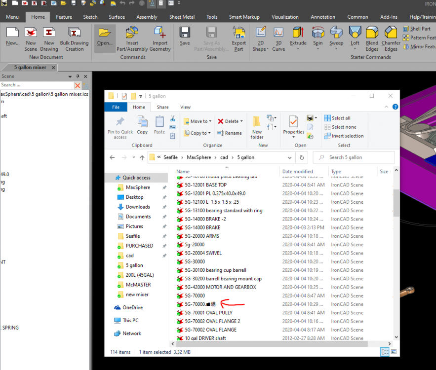
I had just done a lot of work about 1.5 hours, and hit save, I normally do not let it get this long before saving but I was in a grove and forgot. Ironcad Refused to let me save as normal and instead forced a save all as external on me. After trying many different ways to save, the short cut the file save menu, double checking that i was clicking the correct option, checking in windows file manager that the file was not set to read only, I had no choice but to save all the files as external wasting the next 45 minutes of my life, making a giant mess of my directory and having duplicate names. On top of that Ironcad shoved random Chinese caricatures in some of the file names. It works fine on restart Anyone else experienced this?
-
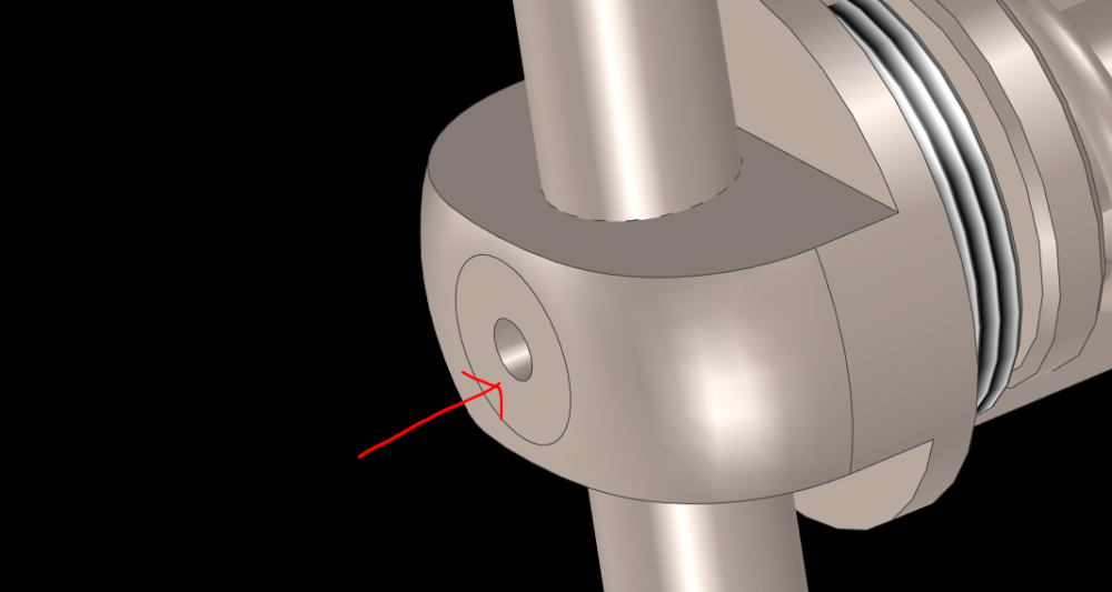
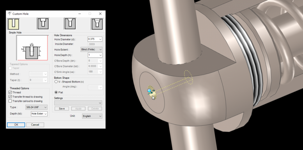
Did something change as to how IronCAD shows threaded holes? Since 2020 whenever I use the custom hole tool to make a threaded hole, it does not show any representation that there are threads in the hole.
-
Is there a way to do that with assemblies too?
-
Is there a quick way to move the triball to an attachment point? I find that i spend a lot of time getting the tribal to an exact location, positioning my part or assembly from there, then working on something else, and when I come back to that part I want a quick way to get the tribal back to that exact location again. Some times there are a few locations on the part that I want to quickly shift the triball back and forth from. I have tried making attachment points at the locations but I can't find any quick way to move the triball back to them. Thanks Brent
-
Your Top 10 list of most useful tools in IronCAD
bmckelvie replied to tlehnhaeuser's topic in General Discussion
For me its the Boolean operations. I have a lot of complex shapes that i often need to mate with each other. A simple copy/linking of one, then using it as a negative on the other part and i have the easiest match possible. -
Is there a way to disable the radial menu that pops up on every click in Ironcad? it is eternally in my way and I don't see it in settings.
-
Is there a way to convert a scene from mm to inches? I made a scene under a mm template so all my units are currently 1mm = 1in
-
Hello, I am setting up my drawing templates and want to change the pen style for hatches. I have made a new line type for hatches to use, but cant find where to (in the template) tell IronCad to default hatches to using that style.
-
Thanks for the replies, I am using the windows 10 print to pdf as an alternative for now.
-
When i try to export a drawing (In ironcad draw) to pdf i get some odd behavior. It strips away many of the parts in the drawing, but leaves the bom balloons. THe exported PDF is missing the parts, and the icd file is missing them too. If i do a view update they come back but my PDF is unusable. Any ideas on how to fix this?
-
Thanks, that is a lot closer to what I was looking for.
-
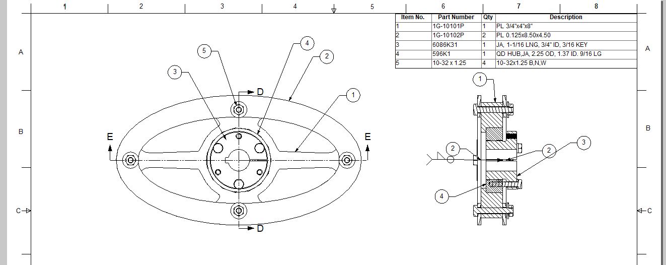
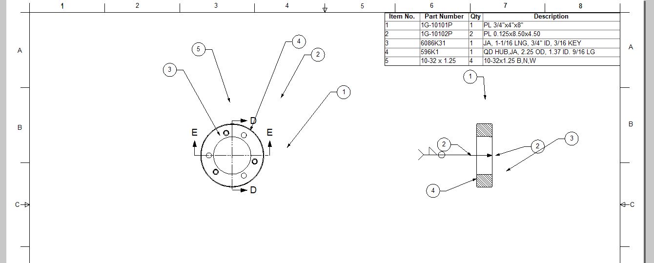
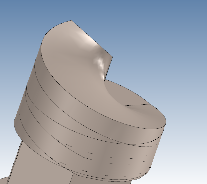
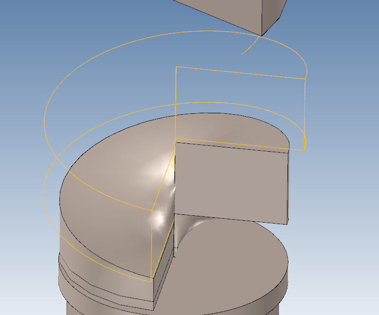
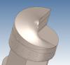
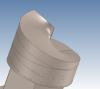
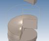
I found a way but I am not overly happy with the results and found a lot of bugs an limitations in the process. Using loft I created 2 rectangles 270 degrees apart from each other, and the second one higher than the first. Then I created spiral 3d sketches that went from corner to corner of the rectangles. See Gate_3.png Then in the loft command I used the important point feature to correct IronCads bizarre default choices for where to loft too. Ironcad unfortunately leaves weird artifacts around the loft, I sort of got around them by making my loft a larger diameter than it needed to be and then using a hollow pipe to trim the outsides neat. I also had to work around the fact that Ironcad can not loft to the second rectangle if its bottom corner is the same point and the first rectangles top corner. I got around this by leaving a space, then duplicating the loft lower to fill in the open area left by the workaround. There are still a few artifacts I need to get rid of, but it is getting close to what I wanted I attached a few pictures to try to make more sense of this.
-
I have been racking my head trying to figure out how to do this in IronCad I am trying to model a spiral that starts flat and ends up vertical 270 degrees away. Think of a thread or auger flute but without the shaft in the middle and that only makes one 270 Degree rotation. I am using it as a gate to control flow, on the flat full flow will be allowed through then if I rotate 270 degrees, no flow will occur.
-
I have had a few clients who i have recommend use compose to review the models or drawingsI make for them. Its a great tool but has 2 major pitfalls which I believe are hurting Ironcads' image. 1. The clients absolutely hate that they have to download the complete ironcad suit to use it. They hate it to the point of swearing and indicating that they hate Ironcad which is the exact opposite reaction I/we as a user group wants. A way better and less intrusive option would be the startup splash screen saying they can get a free trial of Ironcad and give the link. 2. every time Ironcad updates anyone using only compose needs to automatically update too. It looks really bad on Ironcad when i have to fight every 6 months trying to get clients to be capable of just looking at models. The way I see it, Compose is many peoples first step into the Ironcad world. It needs to be seamless and perfect. Sorry about the rant Brent
-
Will IronCad auto update to 2017 through the update utility or do I need to download the new version manually?
-
Thanks Kevin, I will look into it
-
Does IronCad have the ability to allow users to custom generate scripts or addons for it? If so what language does it use. I want to make a script that does something like IronPros feature of clicking on a part and making an unfolded sheetmetal drawing, expect I want to make profile cut outlines. the exact plan is I click on a part hit the button and have it generate two 1:1 views with 3 outside dimensions (Length, width height), a simple title block that accepts input for part name, qty, and material. Then export it as a dxf. (if I get proactive I may include a feature to automatically remove threaded holes, or any hole that has a diameter less than the thickness of the material) Alternatively if there is a preexisting add on similar to this let me know
-
As a test i made the piece with the holes in it thicker (1 inch from 1/4") the hidden lines showed up correctly then, so it is Iron Cad deciding to draw the part this way. I checked the hidden line dash size pattern and it is dash 0.039" space 0.031" adding them up does not make 1/4" so it does not make sense to me that it shows up as a solid line in the drawing. Thanks for the Video Kevin, i did not clue in that I could make a new line style, that is quite handy and I will definitely use it and I am adding it to my drawing template now. Is there anyway to automate the process of IC drawing picking the hidden line type to mach the drawing?
-
If you want a free solution, blender, has similar physics capabilities, I don't know if it can tell you optimal fill but it can fill a container with any shaped object
-
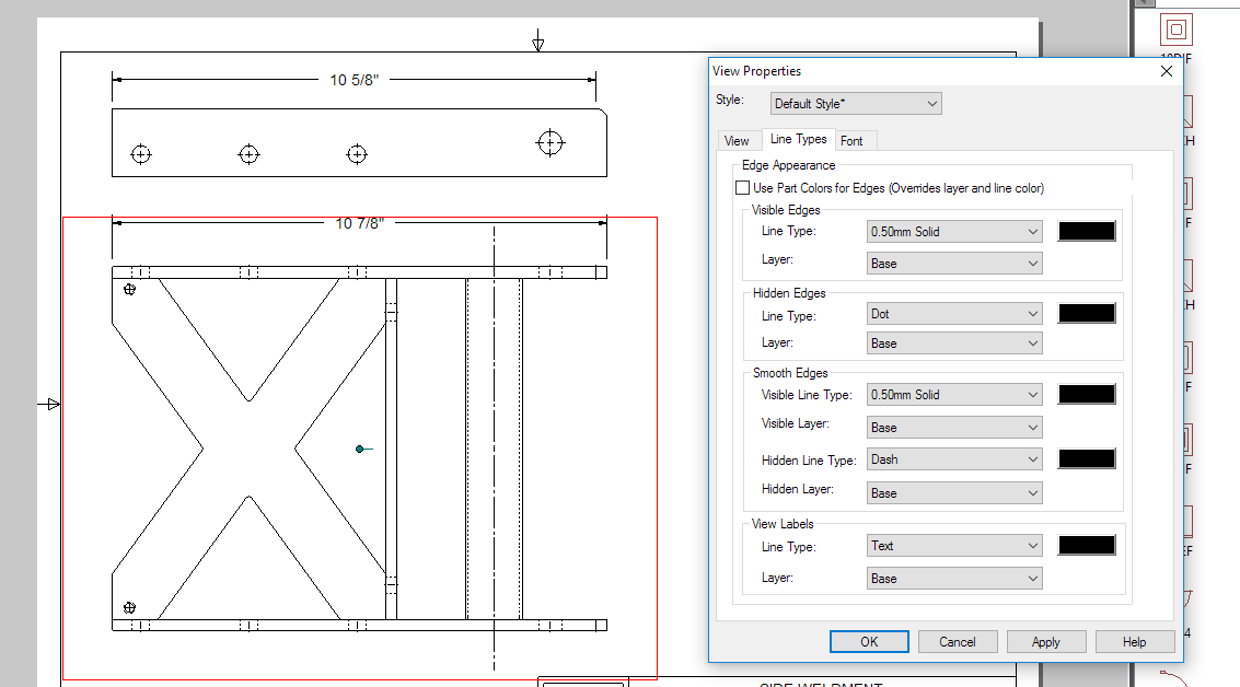
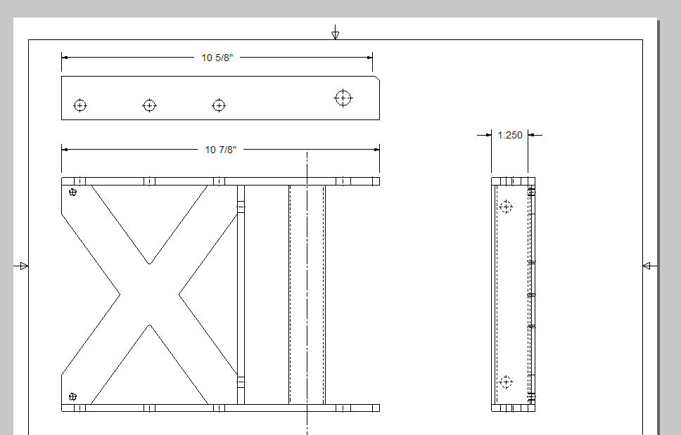
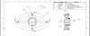
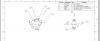
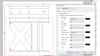
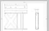
I have struggled with this for a while, In my drawings i modified the hidden line style to make sense on the drawing size I am using, you can see on pic one, The problem is the hidden holes do not appear to follow the same style and remain solid lines. I can not find any option to set their style. I am working around this by using view properties and setting hidden lines too dot. (see pic 2) Is there a way to change the hidden line style of the holes, or better yet get them to use the sheet hidden line styles?
-
I am attempting to use the new 2016 feature of making a bom based on a view, but the balloons are using the numbers from my main assembly, Is there any way to make the follow the sheet bom? Thanks Brent
-
My work flow is I have a main assembly with everything in it, I set all my sub assemblies to treat as part, in this instance only (part /assembly properties in the tree) and I save all my subassemblies as separate files. I place the first bom with that one, then on the following sheets i manually select the subassemblies from the hd and the bom tool automatically has the right info in it. I can't say if it's the most efficient, but I have a lot of control over what is displayed this way. The new select view in pu1 sounds really promising so I will try it out.
-
Thanks for the tips, they both are really helpful. I actually do have the newest Ironcad, i just did not know about the pattern feature along edge feature. I love when i learn about a new feature of the software! edit: I actually ended up using the first method because the pattern feature along edge changes the spacing along the edge but the extracted curve keeps it consistant
-
I am trying to copy or link a pattern along a curve, but when I do the fist instance starts at half the distance of the specified copy distance, which then offsets all of the patterned instances. Any ideas on other methods to achieve this, It's holding up production on a part I need to make so any help would be greatly appreciated. Brent link_along_curve.avi