


bmckelvie
-
Posts
148 -
Joined
-
Last visited
Content Type
Profiles
Forums
Blogs
Downloads
Articles
Gallery
Posts posted by bmckelvie
-
-
That helps as long as I remember to do it before importing anything onto the sheet. Still does not fix the weird mix of metric and imperial on the same callout. Not that I am using them.
-
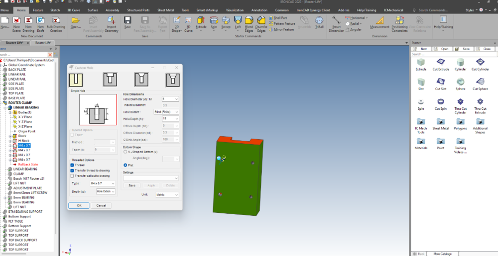
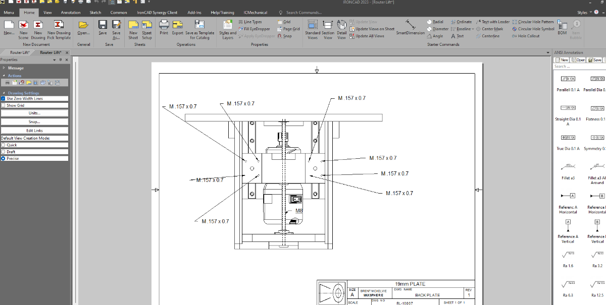
I used to be able to disable the callout transfer to drawing, so it did not ruin all my drawings. Now I can't disable it, and it is not showing metric threads correctly. I remove the transfer option in the custom hole tool, and it still shows in my drawings. It also moved from saying M4x0.7 to M0.157x0.7 which is bastardizing the callout between metric and imperial.
-
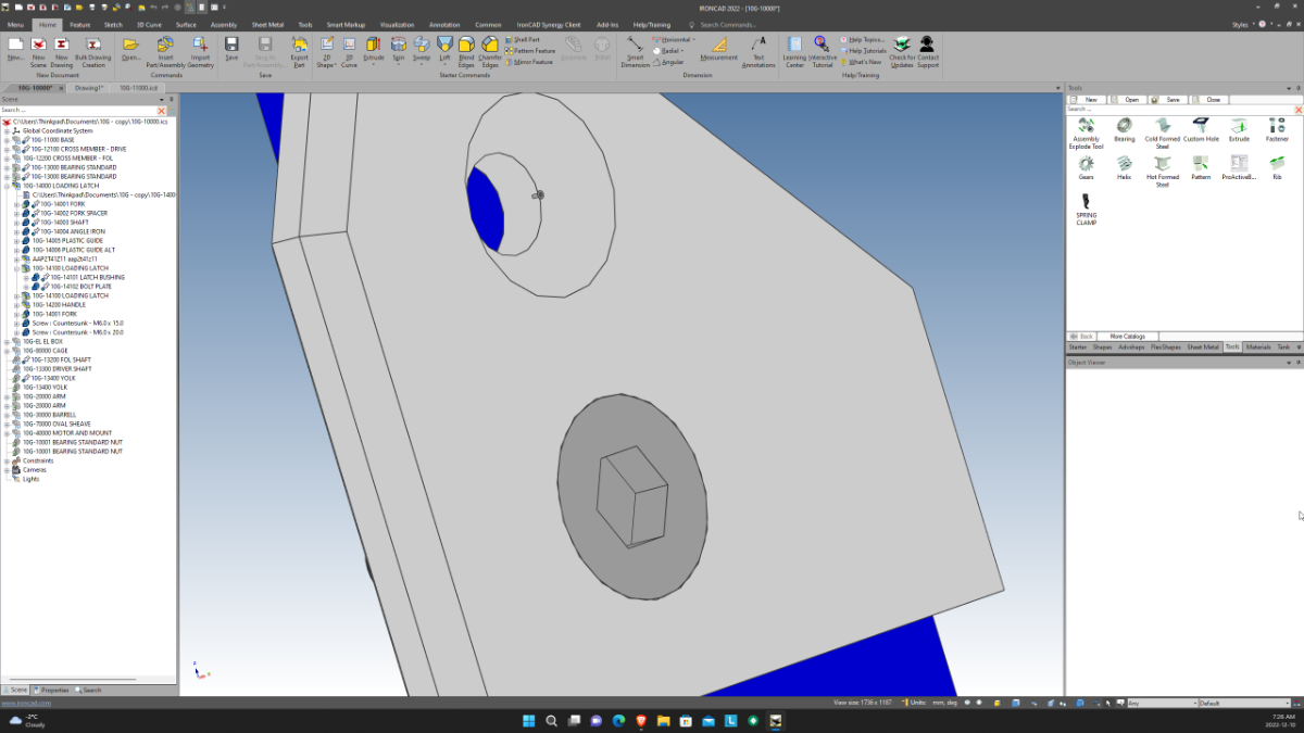
When swaping between windows, specifically in my case from swapping between a drawing and its model, every time I go back to the model, the catalog window grows.
Click away and click back and it looks like this. it keeps doing this until it has taken over my entire screen

-
 1
1
-
-
Thanks that worked well!
Brent
-
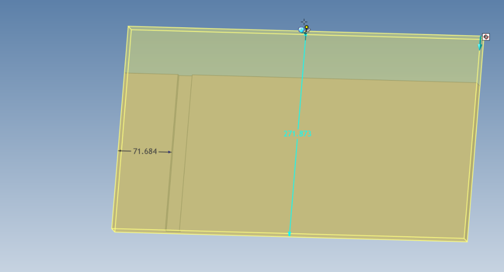
Hi Everyone,
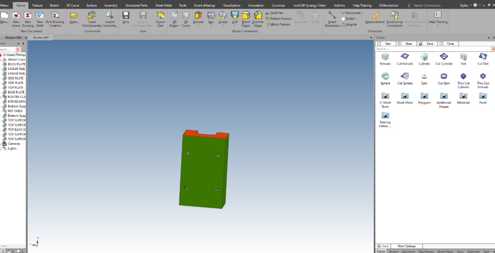
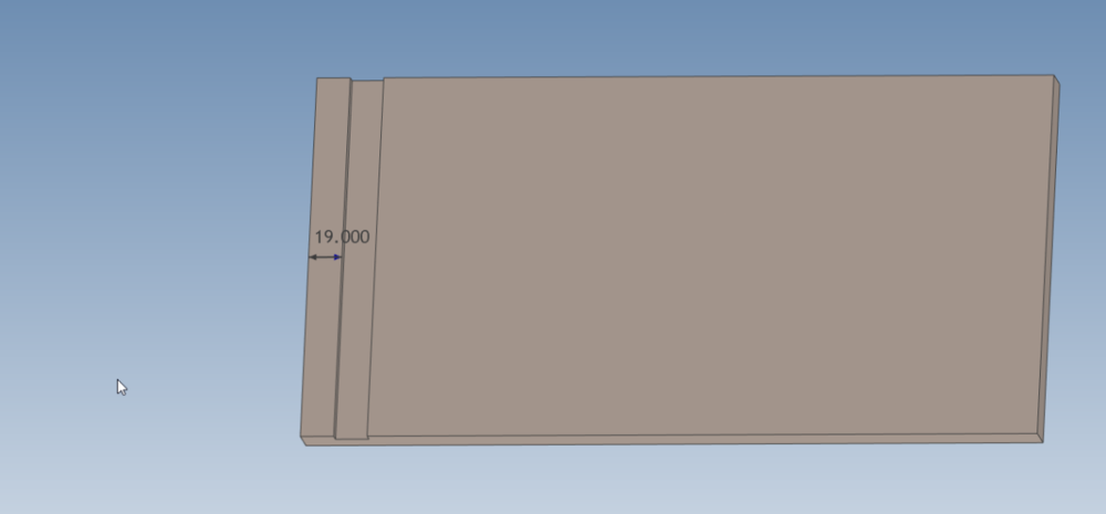
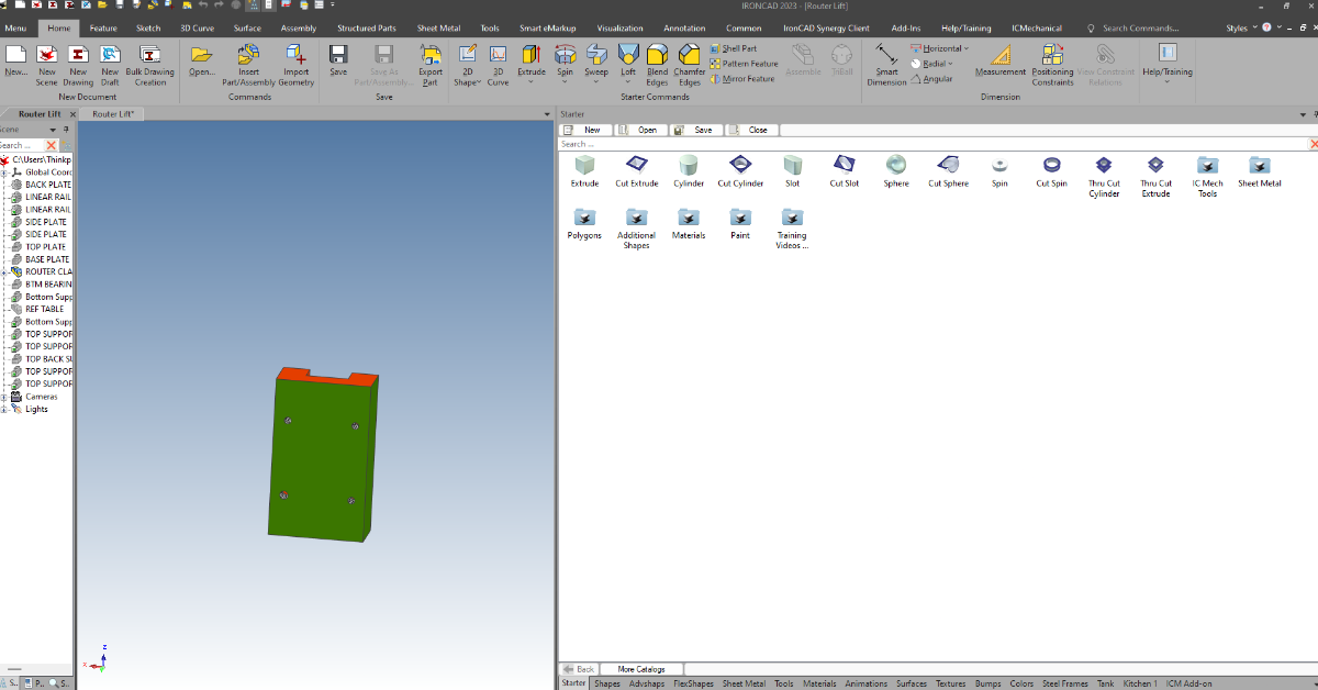
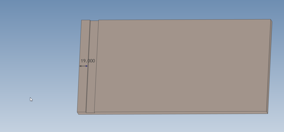
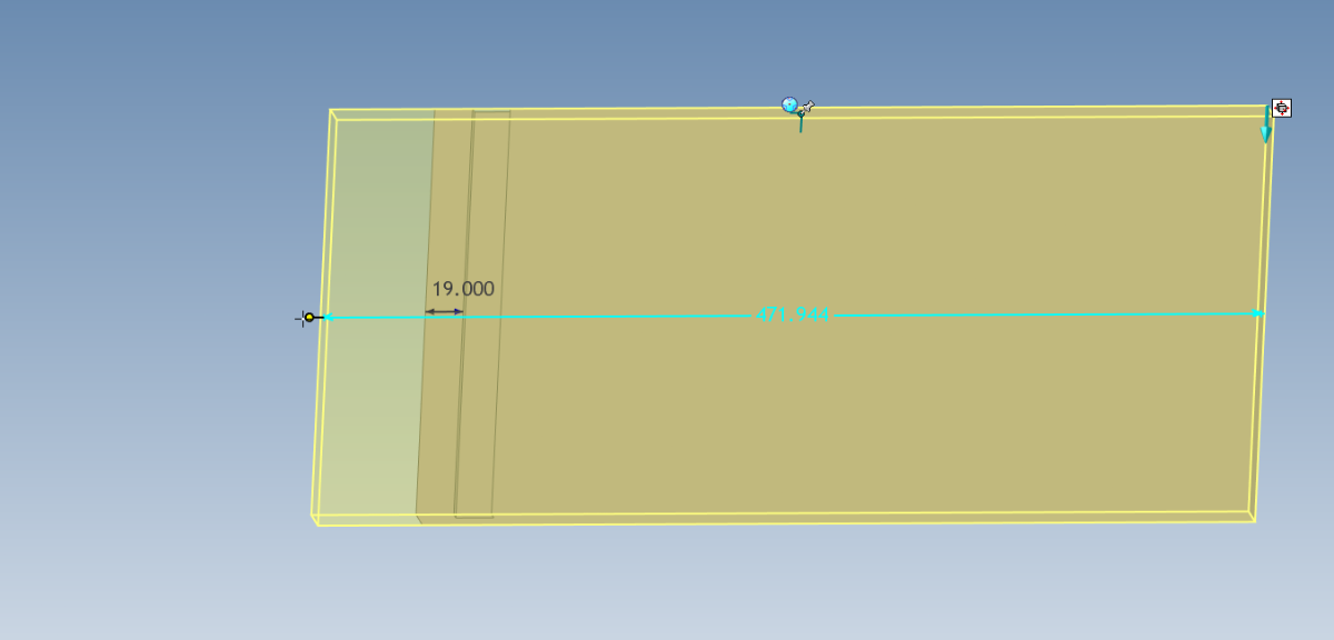
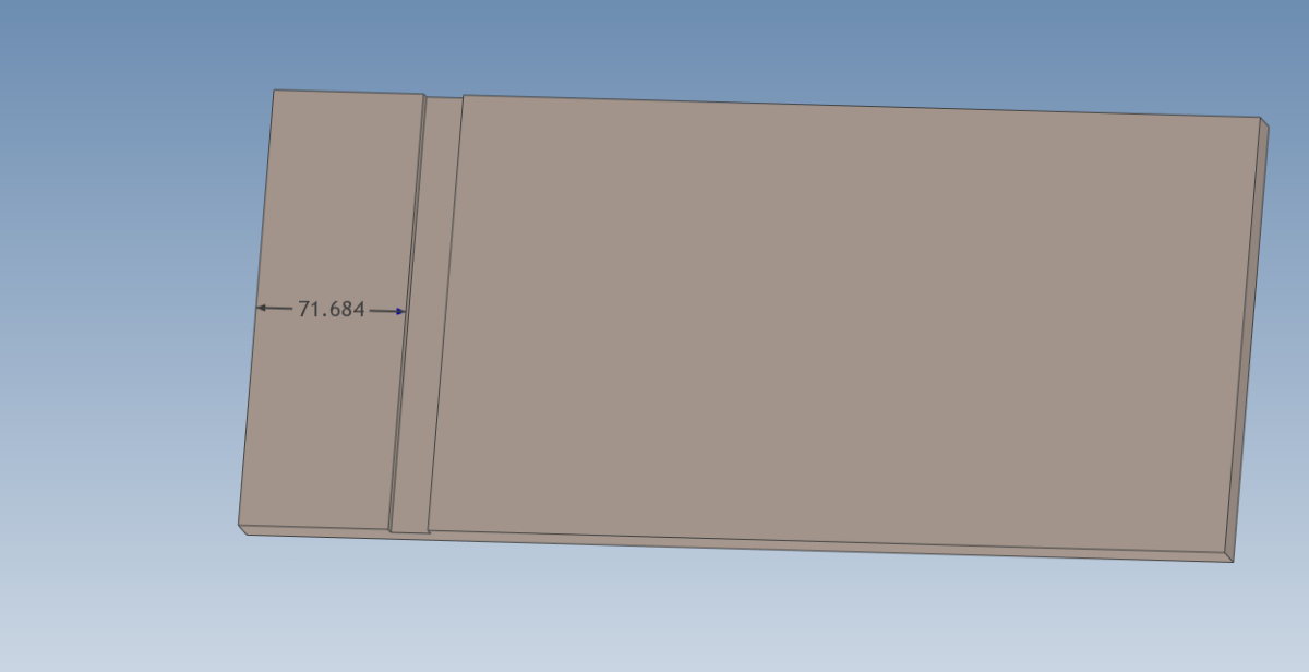
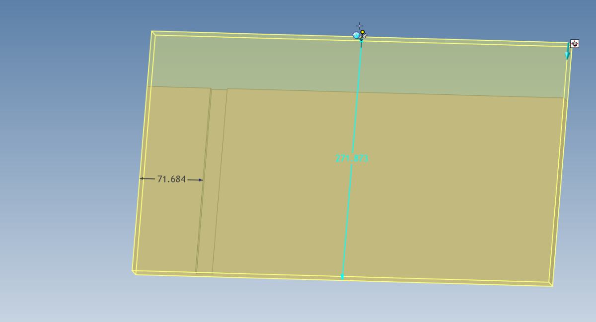
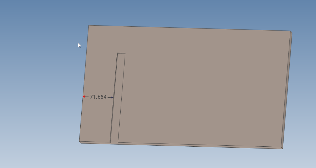
I have tried making a structured part, with a slot in it extruding through the part and staying 19mm off of 1 end. when I resize the base I want the slot to resize with the main part, and stay 19mm away from the end. Is there a way to do this?
In my attempts, I give the slot a smart dim I want it to follow, but when resizing it ignores it. and if i try to resize in plane with the slot, it does not grow with my part.
Brent


-
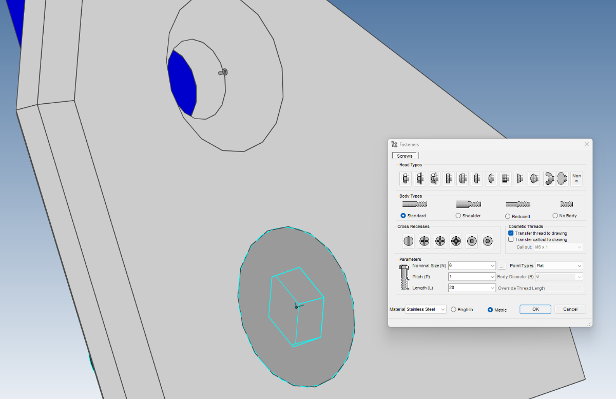
I placed 2 m6x1 20mm long FHCS's in my model. I decided to change them to 15mm long. when i use the item properties to do this, it shrinks my screw down to basically nothing
Addon properties for the 15mm long screw
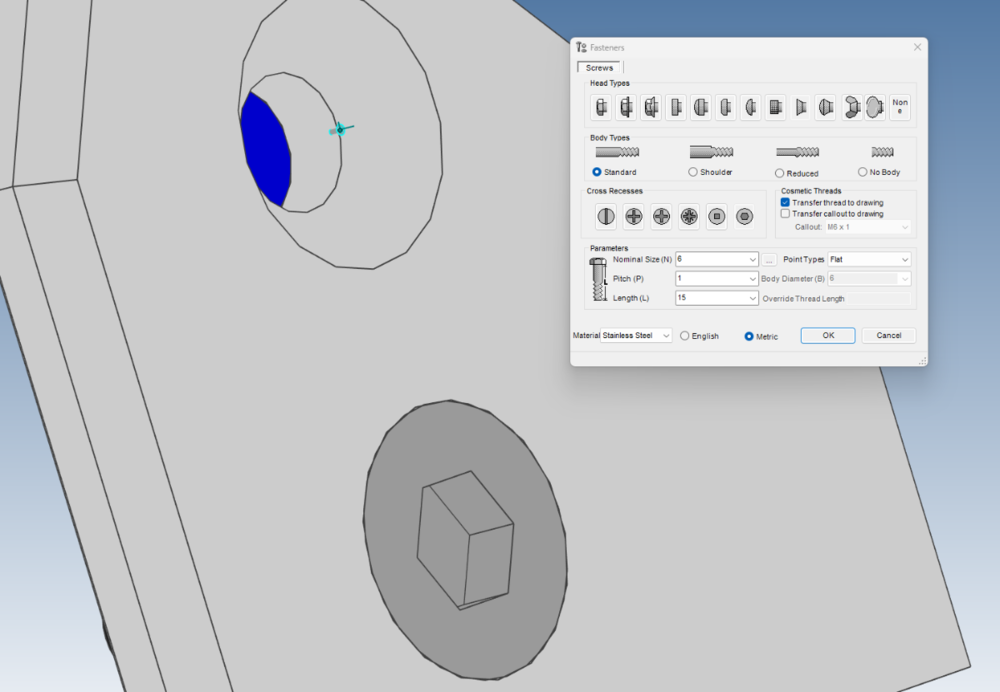
Addon Properties for the 20mm long screw


-
I wish I had started these drawings in CAXA, but everytime I try i run into other issues.
I have updated, and I have even tried making a new drawing. still does not show qty.
-
Thanks for that, I had forgotten about that sheet setup page, but even with it on, it is still not showing the # of holes
-
Hi Everyone,
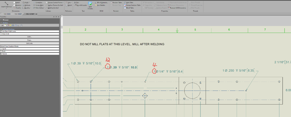
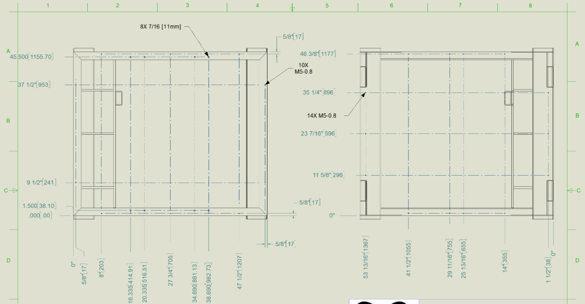
When using the hole callout tool, I have noticed some oddities, that are probably me not knowing how to use it as intended. hopefully someone can shed some light on them.
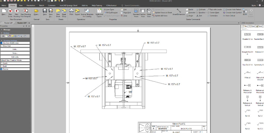
1. In my screen shot I have tried making the holes in many different ways, linking, patterns just making them all independent. and no matter what I do it only ever shows 1 as a qty, I would think that it should grab all the holes on the part of the same size and use that for the qty number. Is there a way to make it do this?
2. Why does when dual dimensioning is enabled, does it only dual dimension the depth but not the diameter?
3. Why does it not grab thread data from the model? I find that I have to manually type in the thread data for all my threaded holes which is really a bad practice (If i change my threads, my drawing will not update leaving a bad drawing). If I use transfer thread data to drawing when making the hole in modeling, it pollutes all the drawings and makes them all unreadable, then I spend all my time hiding thread data from 20 other levels that are not needed. So it appears that my options are, show thread data on all drawing and assembly levels, or manually type it in where I want it. Both of which are bad time consuming options. So I figure I must be missing something.
Brent
-
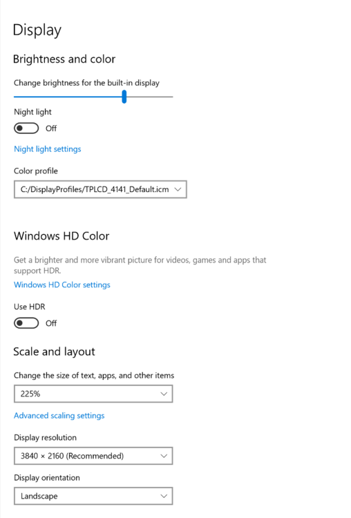
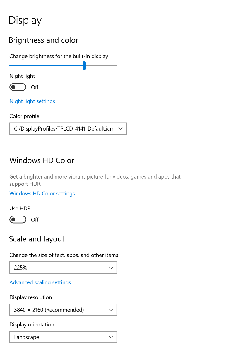
Playing with it, and turning all scaling off seems to fix it. but then everything is so small that I can't see it.
It cleans up the weird buttons on the view as well.
So for Ironcad to be useful to me on this laptop, it looks like the scaling needs some work.
-
These are my display settings, I am scaling it because otherwise I find it unusable for other reasons,
-
@IronKevinKevin where do I send the files?
-
Thanks I will try the suggestions.
@SSIMMONSNo its the built in monitor on my laptop. it is a 4k screen that I have turned down to something reasonable though
-
I have ran into an issue where when I try and make a new drawing and i create a standard view, the view windows both does not update, so i can't tell what part I am selecting as well as it never highlights which views I am choosing to use. so its a guess as to what i actually will have on my drawing.
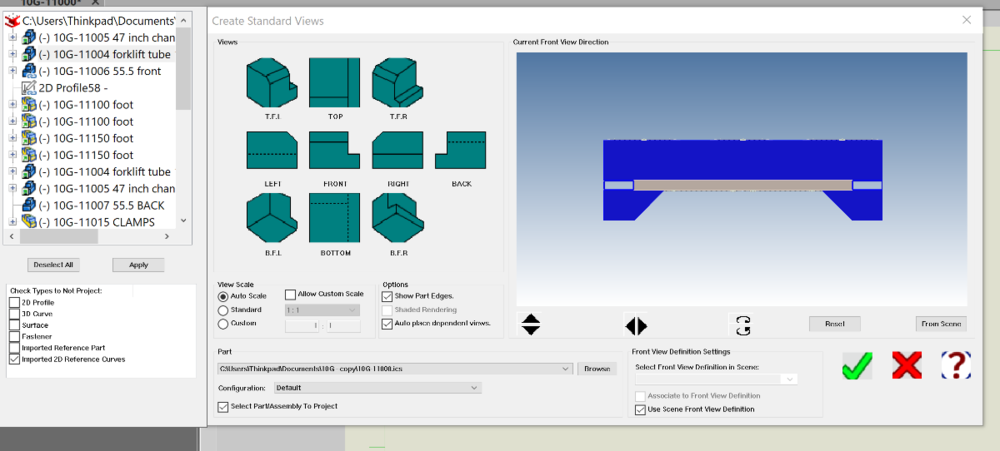
-
Does anyone else get this problem?
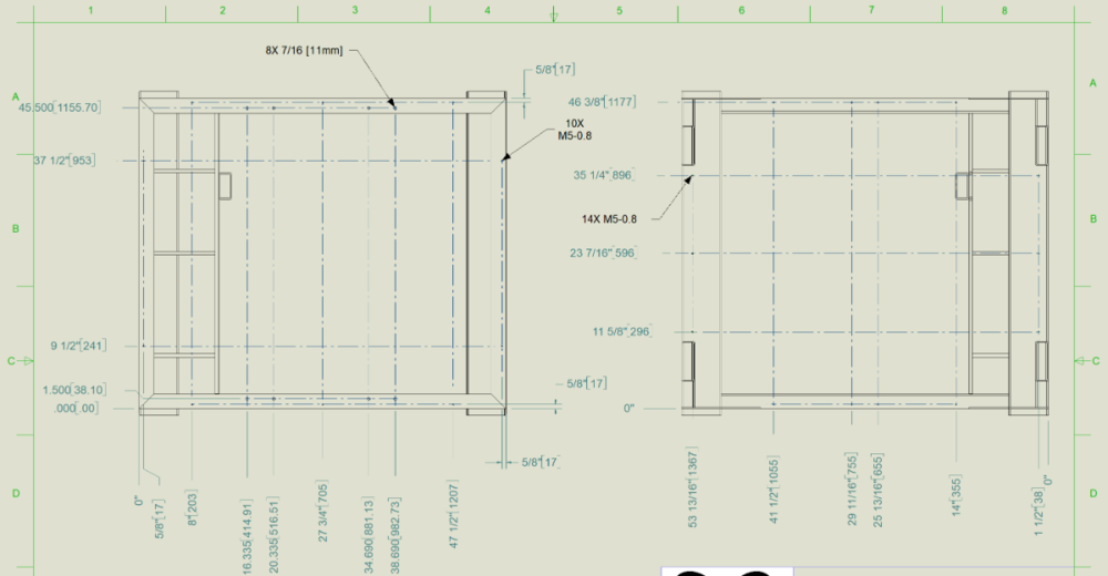
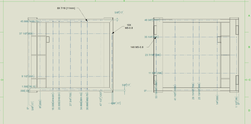
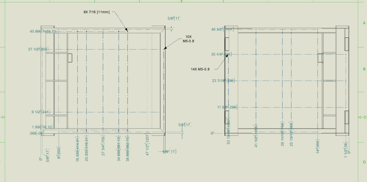
Its infuriating, every time a sheet updates it repositions all my dimensions. Usually not by much but that's still enough to make a mess of the drawings. So I am spending all my time fixing drawings I have already made instead of making new ones.
There is 2 screenshots of 2 positions it jumped to randomly on view update. I find every drawing will do this, some more than others. Its really disheartening to need to go back and fix hours/days of drawings that should not change. This has been an issue for at least 5 years now.
Brent
-
Hello,
I have a common part that I use in many different assemblies, I keep it in a catalog to make it really easy to insert. The issue is if I pull in more than one, they are not linked so they show up as separate instances in the BOM. Is there a way to make them linked?
-
I did not release that there are 2 different pack options in Ironcad.
I just used the Pack and Go option instead of the File menu Pack option. It works a little better but it still has Major issues.
1. It has 3 main options, the first is to unlink all files and save everything to a single scene file. This works fine. Breaks all the external links so its not a faithful copy of the original so it requires all new drawings to be made.
2. Copy all selected files in a scene into a folder
3. Copy all selected files in a scene into a zip
2 & 3 work the same. and are very close to what should happen. They copy all the files make the exact directory structure again in a new folder, it even copies all the drawings which is great! But then it stumbles on the last step, it leaves all the files pointed at the old files. So you have basically just made a bunch of copies that do not do anything. They need to all get pointed to the new files.
Kevin I emailed the zip to you, but all the references will be looking at the wrong place.
-
The files are on my main HD under documents, I am using Pack Copy from the file menu.
I will try to get all the files together, like I said they are all over the place so it will take some time
-
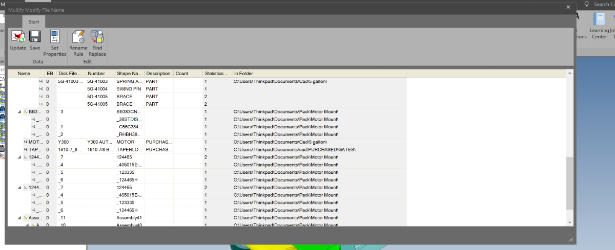
Hello, A few days ago i started a topic on how to create a new version of an existing model/assembly. It was suggested to use Pack, and it seemed to work.
I just tried it again today and it left half of the files in the original directory making the pack copy not work. You can see in the screenshot that many of the files are not in the pack directory. I need to be able to pack a version of this to be portable to give to another engineer. (It would be even better if there was a pack all drawings associated with these files as an option too.)
Does anyone have experience getting pack to work on assemblies that have external assemblies and parts inside of them?
Brent

-
Thanks everyone, I tried everything in order of how they were written here. Kevin's suggestion finally got it.
Can we add this as a bug that needs fixing? Yes I can go though regedit every time I unplug my external monitor but that is really not a great long term solution. Regedit can really mess up a computer if you delete the wrong entry.
Thanks again,
Brent
-
Hello, I had to take my IronCad laptop on the road with me. So I do not have my multi monitor setup with me. Problem is now all my sub menus open on the now non existent monitor and I can not get them back.
I have tried cascade all windows, changing resolution. changing the connected monitor settings, using ctl shift M and arrow keys. Nothing seems to find the menus. So my ironcad is completely unusable right now.
Any one else have this, and figured out a way to get everything back on one monitor, and a way to keep everything on one monitor.
Brent
-
Thanks for the reply,
Copying the entire dir will not work in my case, to many files in different locations.
The pack and go is mostly working. I will still need to remake all my drawings but it looks like it is at least possible to save my old designs.
-
Starting to get frus trated with this one.
I have a project that I made a while ago, it pulls in a lot of external Ironcad files in different directories.
I want to save all the files to a new dir so I can go through rename, clean it up and make some improvements to the design.
I have sold the existing machine to many customers so I want to keep all the records from changing, ie I need a permanent copy of the drawings and models.
Every time I try to save it all to a new dir then go back and start modifying the new files, i find that some will inevitably still be pointing back at the originals?1 I have 6 different copies now on my hd, and every time I try to clean it up it just gets worse.
So does anyone have a way to do this? Bonus points if there is a way to keep the drawings too.
-
Wow, that is really neat. I am going to have to invest some time in refining my catalog parts to follow this.


Catalog bug Ironcad 2023 SP1
in General Discussion
Posted
That worked, thanks! when it first started doing that it was amusing, then it quickly got old, and from there it got really frustrating.