


Robert Andersson
-
Posts
1,562 -
Joined
-
Last visited
Content Type
Profiles
Forums
Blogs
Downloads
Articles
Gallery
Posts posted by Robert Andersson
-
-
Also,sometimes (in IC) CTRL A regen to update all parts to latest kernel version can help.
-
In addition, you can also Right Drag a block from the Shape catalog and drop it on some part. Then select option "Drop As Assembly Feature" and "AllAssy/ parts...".
That block will now remove volume from all parts.
This feature will show up in the Scene browser also where its scoop can be edited.
-
It depends if you have a hole with thread texture or a hole with physical threads.
With a thread texture the geometry is a simple hole. To see those on a 3DP part you need to export a WRL and print it on a multi color printer (like Projet 660).
Ironcad uses textures to represent threads and the reason is performance and also that screws and bolts are usually purchased, not manufactured.
If you really want a 3DP part with threads you have to create the geometry in Ironcad with tools like the spring/ sweep function.
-
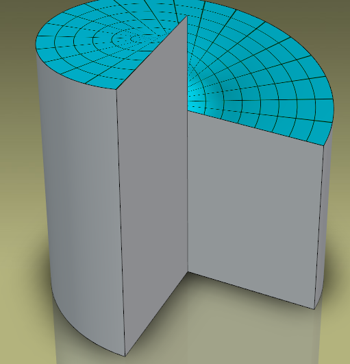
I am not sure exactly what you need but I think you should involve sweep. Loft is a bit to free form.
Maybe this shape can help:

-
Some great effects can be achieved if you animate animate colors, transparency and reflections in Ironcad.
Here is a short video explaining the basics on how to:
-
By the way, you can now also animate colors and transparency:
-
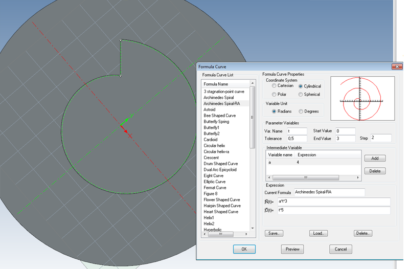
Maybe a Formula curve can do the job.
-
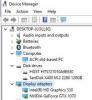
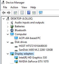
You have 2 display adapters?
-
Computer: Notebook HP Elitebook 8760w
Processor: intel i7 2 GHZ
Ram Memory: 8GB
Graphics Card: nVideo Quadro 300m
Performance classification: 7.1
Hard Drive: C:= Flash 256, D: Iron 1TB
Operating System: Windows 7 PRO
-
I have newer seen this strange problem. Could be a hardware failure.
-Is it still there if you use Software rendering?
-Maybe you have installed or updated another Graphic software that is conflicting with Ironcad?
I would test things like:
-emty user TMP folder.
-un/ Re-install Ironcad. Maybe to a different folder (path).
-change Graphics card. Can be hard in a notebook.
-a long shot is that a Windows update caused this.
-
It can be a good idea to link out the sheet metal part also.
Takes away the problem with orientation in space.
-
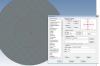
-Apply the texture and export a WRL file and print the lime on a full color 3d printer like a ProJet 660.
-maybe you can use this software to convert a image to a 3D surface with deeps depending on the pixel color:
www.mr-soft.net/en/bmp2cnc.html
Not sure it can convert to a spherical surface do...
-
This can be tricky.
You want to let the customer work with your assy but the customer should not have all info so they can take over the project and manufacture them self...
Tricks that may help could be:
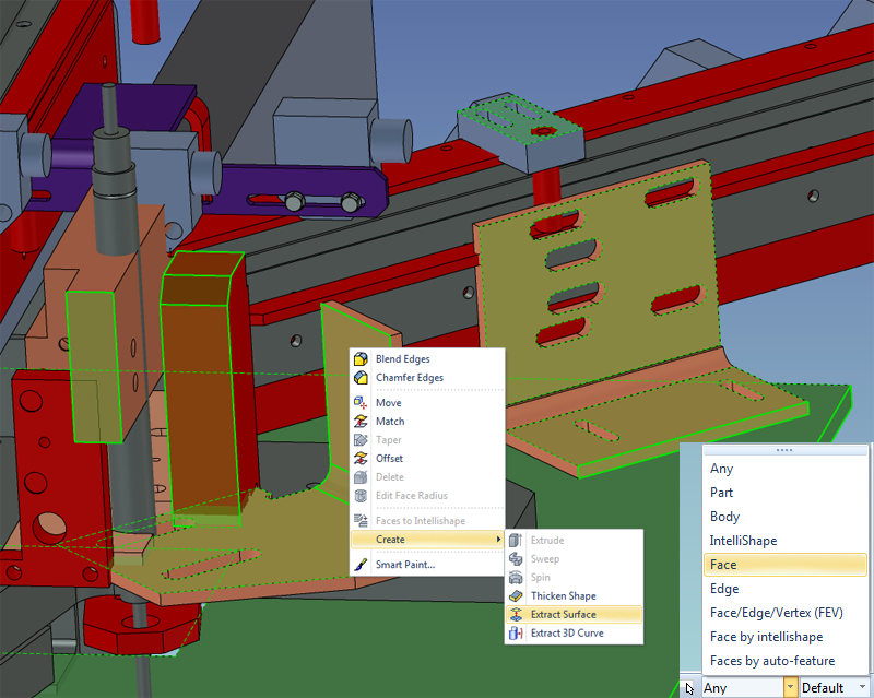
-Select multiple surfaces of your assembly solids (light in green) and RMB and select CREATE SURFACE MODEL
The surfaces should be the important ones especially the connecting and bordering ones and those that are needed for the looks.
Use SHIFT click or BOX select or a combo of those.
Export the resulting single surface part as a STP and send to the customer.
-Do a boolean of all the parts in the assy. They then become one single part. This makes it a little harder to use.
Export the resulting part as a STP and send to the customer.
-Scale the assy with a random scale factor (hehe)
-Export a facet model like STL
-
It is gray until you save your ICS file.
After save you can upload to GrabCad using that button.
-
-
-
think T is WAY to far away for the Triball
 haha
hahaI like the left most key § for the Triball.
There are Different Keyboard layouts per language of course.
-
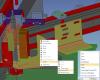
Connect Keyboard to a command in IRONCAD
This is an example when connecting a keyboard key to a command makes daily work smother.
In this case the key H is connected to the command HIDE (Selected).
If you forget what key you applied, Ironcad reminds you in clear text when the menu is shown.
-
While at the subject, if you use IronPRO XT you could have use of the tool called "Export Un folded Part".
Should be the same with Ironcad mechanical.
Drag and drop the tool on the "base" surface of a sheet metal part and you will instantly have a flattened DXF version file created, forced to scale 1:1.
This tool will unfold the sheet metal part, then export it to a 2D DXF using a custom ICD template.
Also,
There is another tool called "Faces To DXF" that exports a face of a solid to a DXF file.
Can be found in the IronPRO_XT Tools.icc catalog.
-The face selected do not have to be a sheet metal part.
-
You could deassembly all assemblies. That will remove all assys in the scene and leave just parts at the root level in the scene browser.
Then select all parts (box select or SHIFT/ CTRL click in scene or browser)
Then Feature/ Modify/ Boolean. Then all parts should be joined to one single part that you could export.
-
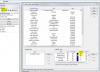
This is a screen dump with Ironcad 2015 at 4K screen resolution.
No performance issues. Lots of space.

-
I had that to on 2 computers. Cameras are disappearing when moving around. Also goes for a new window to the same scene.
-
Best method for this is to split the scene window vertically in two. Then assign different cameras to the scene views. Then you can see what you are doing clearly.
-
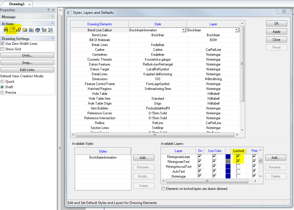
That template of yours have some locked layers.
UN-lock them to edit.

Cross Sections
in Tips and Tricks
Posted
This could help you: