cborer
-
Posts
2,260 -
Joined
-
Last visited
Content Type
Profiles
Forums
Blogs
Downloads
Articles
Gallery
Everything posted by cborer
-
Ah! OK Thanks Mike! That's easier!
-
I fight with that too! ....often! Here it would be nice to see it better. Often I cannot find the problem, means wrong lines. Maybe an extra highlight would help. "Glow wrong" Or: Suppress the working / good curves...so we can only see the problems? Or: Show it by circle around it
-
Thank you both To me this keeps a very strange thing. (Thickness and Material) Important to me is that it has nothing to do with the calculation for the unfold. As well as the minimal Radius bend. Maybe it would be good to color the fields that are important for the calculation. But it looks like just the Thickness and the k-factor has an influence. And that's all. It would be nice to describe them as formula fields, maybe with green numbers or so. Many thanks
-
Thanks Tom If it works it is nice....or fine. But a CAD options are complicate enough. If there are fields with no sense I can never be sure what happens. So I have to ask or test. I want to be sure in what I do. If, later, the production is wrong it becomes expensive. So to me it gives no sense. IC Please Hide / delete Gauge field! Many thanks.
-
I have similar after some surface operations. Surfaces and Edge keep being lightening in green. I save and close. Then its away.
-
Thanks Cary Yes You're right create flat is perfectly working for my work. I forgot that there are 2 similar commands. Many thanks But to me you gave no satisfying answer to the Question about the Gauge/Stock: (I keep on it) I want to drive it by thickness in mm. So it would be nice to ignore Gauge, which is also a kind of thickness as I understood? (But I have to put in something!) Means: drive metal sheet stock by Thickness in mm. ? To me it looks as Gauge is not corresponding to mm thickness? I do not understand the connection. Please clarify and please give a simple sample. Many thanks Carlo
-
Many Thanks! This was just a simple test to try to understand what IC does. Normally I want to unfold cones, or two rail sweeps. From existing Solids. (I Love the new possibility to just select any solid surface to create a sheet metal part) So I do not think this will help me. Many thanks anyway.
-
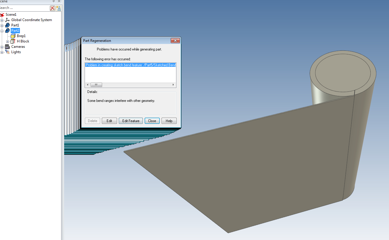
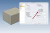
This sample works fine. Thickness and factor 0.33 - Compared to middle line looks correct. Still the factor should be o,5? It disturbs me that I get failure infos.... Also it looks different than this ISO / Din / Ainsi comparison. What is IC using? It is not shown in the options. Unfold_test2.ics


-
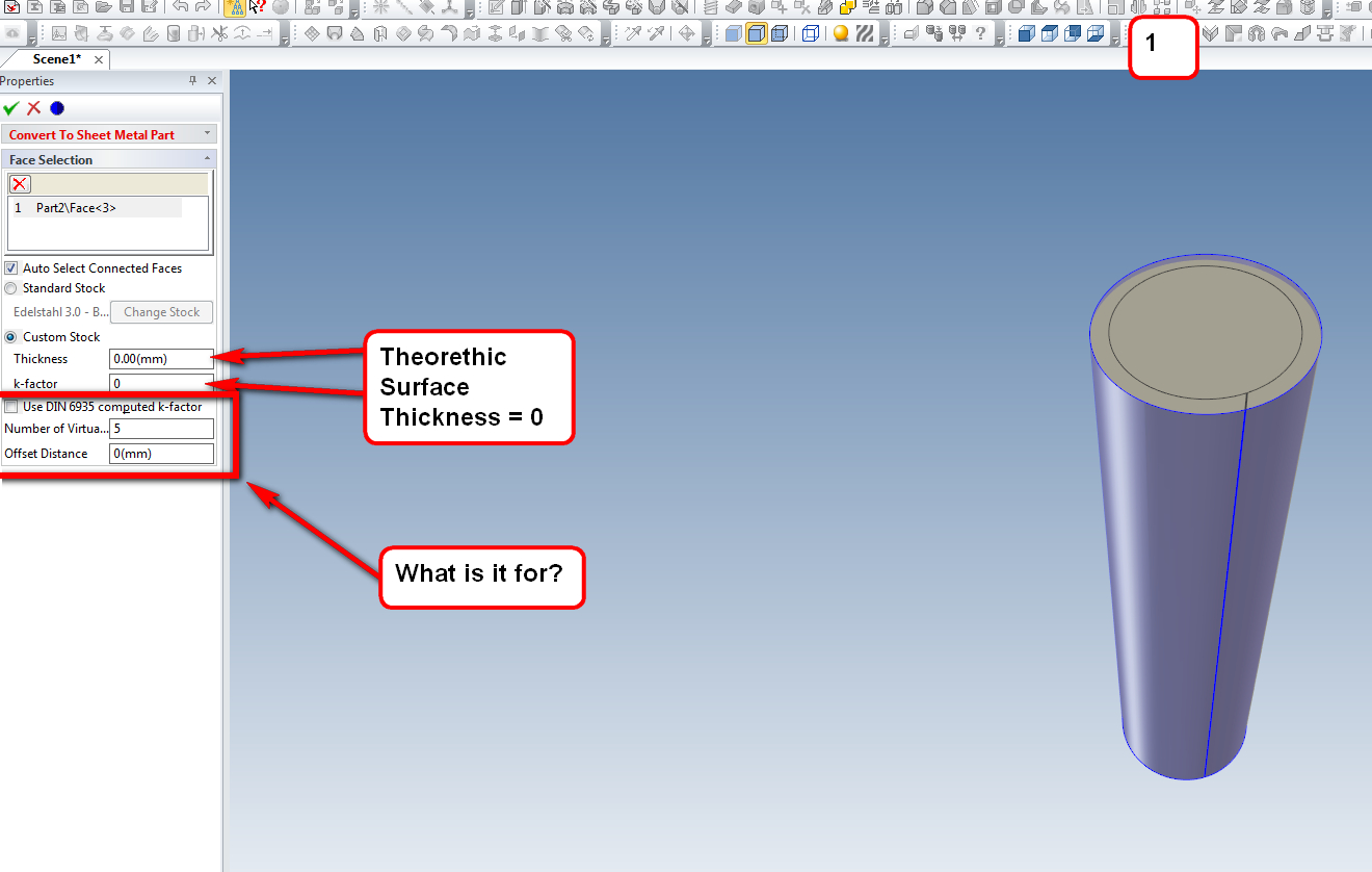
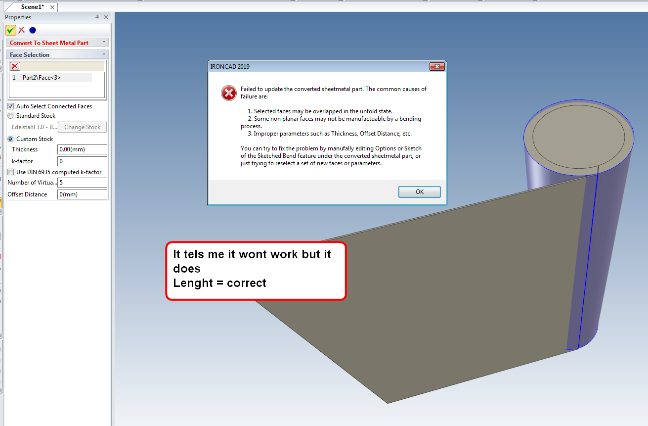
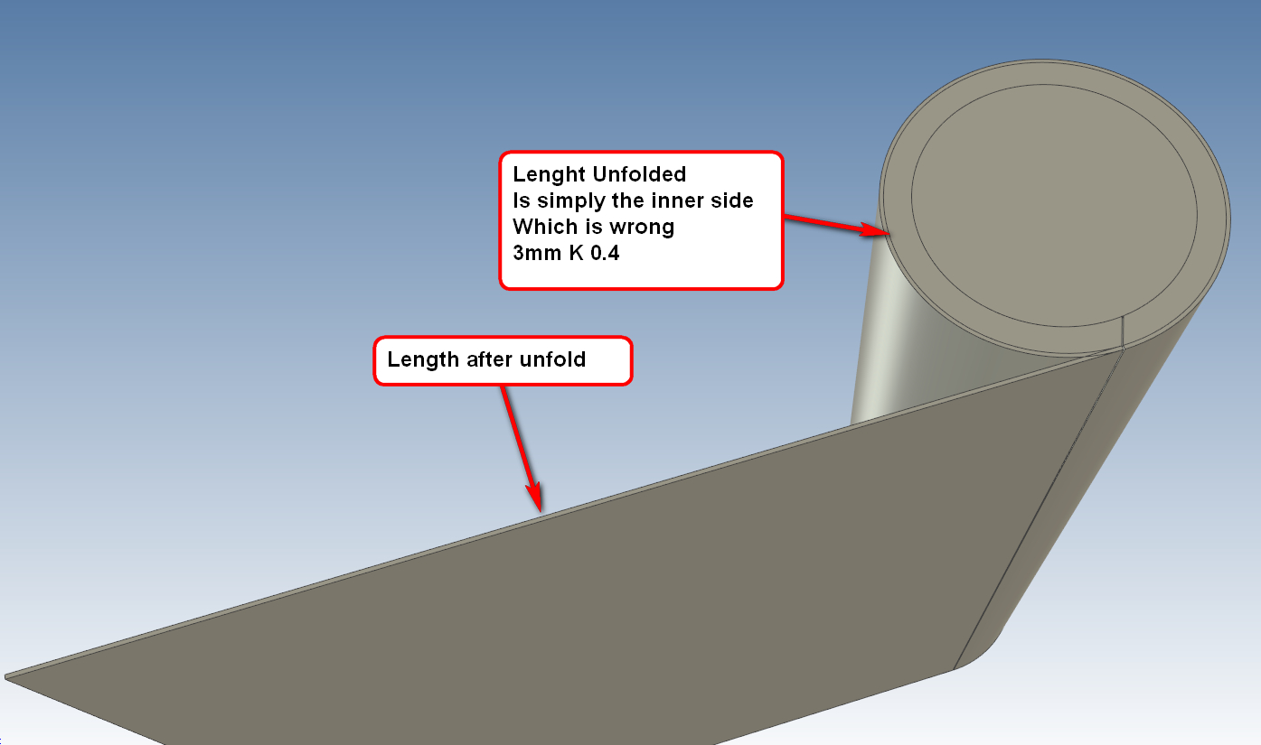
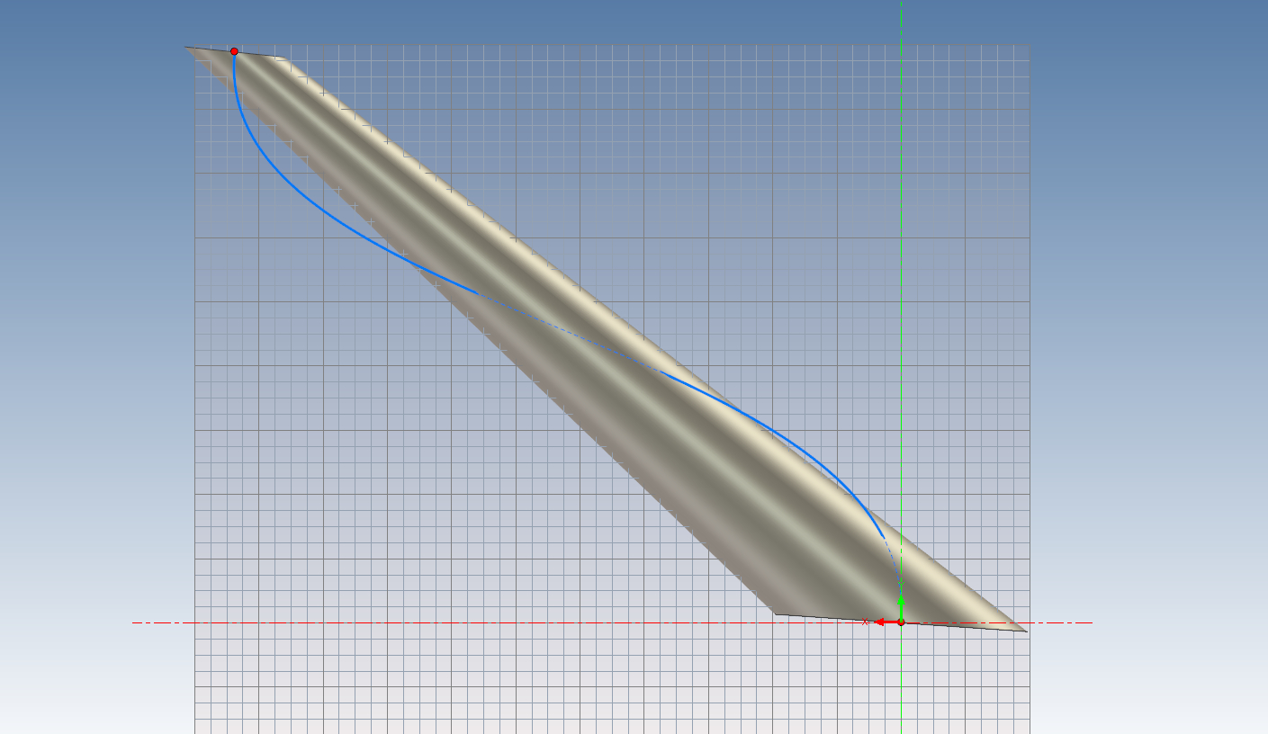
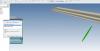
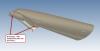
Hi So my first experience with sheetmetall unfold (bend) was great. It works well. Now I remember I've tested long ago the unfolding for curved sheet. I do it since about 20 years in Rhino....but the forward and back is a big work. (I remember IC cannot show the bending lines for curved unfolds) So this time I do not need the bending lines. But now it looks as IC can just unfold stock materials. I do it normally with the middle line with thickness zero. This is relatively precise. Is there a way to do it like that? Or is there a control box to say: Unfold middle line? Or is there an unfold tool for curved surfaces (Cones, Cylinder, 2 Rail Sweep) See pictures Thanks Unfold_test.ics


-
Hi Cary Many thanks It worked perfectly! Best Carlo
-
Hi What is the easiest and fastest way to get a sheetmetal and its unfold from these parts? 3mm / stainless steel ( I am not trained with sheetmetal bend) Thanks Carlo Seiten_Profil.ics
-
Thanks Tom that worked as well with the replay. Thanks Cary yes I confound the match point theme.
-
So I started again by zero I was able to do it with a 3d curve and 3 Cylinders. I do not know why the others did not work... I was able to move the cross sections later with the Triball. That is quite nice.

-
Dear Cary Thank you. I had no much luck in this. Obviously I didn't get it. Can you please post a movie? I tried with a 3d curve as well but it does not work.... Also the edit match point does not work here...... To me it looks like loft tool needs a little revision. Partially I am missing here the intuitive workflow that honors Iron Cad. Loft_1.ics Edit_matchpoint.ics

-
Hi The Loft shape is not what suspected. But I think to remember that IC has a solution for that. In the way the shape consumes or handles the cross sections. Any help is welcome Loft_1.ics


-
Thanks!
-
+1 it became hard to get the handles.
-
As with the discussion about UV curved surfaces: Knot to move would be nice. But it is possible to move relatively easy with 3d curves (less point is better) See movie UV_surface.wmv
-
Hi Cary I struggled over that many times since I installed 2019 to lock the Z axis for rotations (no perspective view) seems very useful to me (and logical) this is a precise maneuver. :-) "versus locking the X and Y and being able to move with the center of the TriBall in this orientation" .... I do not understand this.... can you post a movie? PS of course nobody asks for it if it is there!
-
Thanks for your nice words!
-
Yes thanks for the way....it was a bit too complicate to me. As I am very careful with doing something in the system.
-
Hi Here it is.....
-
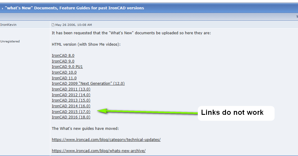
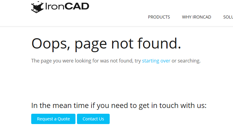
Hi Kevin Thanks The links in the first do not work Please try ....and better delete!


-
Thank you. That works well. Mhh it is really sad that we cannot save in a older version. (old ER) My partner has IC totally new, it would have been nice for him to play with my file......
-
Hi I have an architecture made in IC 2019 My partner has German Version which is still 2018 I want to send him the file. He cannot open it. If I export to older Parasolid or Acis Versions it looses Texture, Transparency, 2d Shapes. What must I do that he can open my .ics file?