


Doug Gower
-
Posts
360 -
Joined
-
Last visited
Content Type
Profiles
Forums
Blogs
Downloads
Articles
Gallery
Posts posted by Doug Gower
-
-
-
I've had problems losing menus too and just wanted to add one thing. I've been able to get menus back by switching back & forth between menu and ribbon bar. It might take a couple tries but it has worked for me when I couldn't do anything else.
-
OK if fillet refers to interior angle maybe radius or blend would work better?
Otherwise, I'm not sure now.

-
Last...
It might be nice if IC gave you the max at tangent instead of the error. That way at least it doesn't fail.
Doesn't seem right that it will work if you cut a circle, but not when using the tool.
-
Thanks Cary. Thanks Eric.
-
First of all I don't understand why this tool is called fillet and not radius? I probably asked that before though.
Either way, when I try to put two fillets together that take up a certain space I get an error. For example if I place two 1/2 inch fillets in the length of an inch I get an error, but if one of them is shorter (or .249") then it works fine. I could understand the error if I was going over the total amount but not if it equals the same amount.
Should I move this to bug report or ?
Here's an example .avi attached that shows the error.
Does anyone know an easy way to do this in order to get the fillets to add up? I can usually manage to get it to work but not as easy as it should be.
-
-
Can IronCAD calculate surface area of one face of a part?
The help file says you can measure the surface area of a planar surface under topic "Assembly/Part/Surface Analysis" but the Anaylsis tool dims out as soon as I select down to the face on a part. This tool only seems to work for the surface area of the part (not a selected plane).
-
Thanks Cary. That worked... and there was some other elements in there besides dimensions that I had to change.
-
Are there any settings to change the font size for the drawing dimensions. I could change these each one at a time but I'd rather make a more permanent change in the setup if you know what I mean... and at the same time it would be nice to change the arrow size.
-
Doug:
It sounds like you are inserting Part1 (as a link) into the Part2 file in order to make permanent changes to Part1 in its original file. You are doing this by saving the Part2 file (which saves the Part1 file via the link), then deleting the linked instance from the Part2 file. Have I got this right?
Eric,
That's right... I tried to recreate the problem with new simple parts and can't repeat it. I like the sounds of your method though.
Kevin,
I'll try to record it later with the original parts and see if I can reproduce it.
Thanks
-
Part1 is linked (inserted as a link)
-
When you copied the features from Part 2, are there any smartdimension on these features? If so, when you copy them to Part 1, they will still exist but may refer to Part2 (geometry) depending on the smartdimension. So if you delete the part, it will tell you the message. But it should only be deleting relations that refer to the part you are deleting (not any original geometry). I'm not sure I'm clear on the issue you are having.
Cary
Yeah, I will come back to this when I get time and try to record it.
-
-
Problem...
I have two parts that are identical in size but each have some different features (holes, pockets, etc). Part 2 has some holes and threads that I want to add to part 1.
So I open part 2 and inserted part 1 into the scene (temporarily). This way I can align the parts together so that when I add the new features (to part 1) I can easily move and copy these into the same locations as part 2 using the tribal.
OK finished with that, I save the scene and delete Part 1... but wait, I get a dialog box...
"One or more parts selected for deletion have a SmartDimension relation. Deleting these parts will remove these dimensions and any parameters associated with the dimensions. Do you want to continue with the deletion?"
Well I thought so... but if I continue I lose everything that was just added.
Is there any way to remove these "smart dimension relations" before I delete the part ...so I can save the new features I added this way? or how else could I do this?
I swear these parts did not have any smart dimensional relations.

BTW - There's nothing about Smart Dimension Relations in the help file that I can find.
-
Did you try compressing or zipping a file to upload?
For the background pictures you might try turning on or off the file extensions for the background. Not sure if that will help... seems like it was something to do with extensions but I can't remember.
If so, it might help for uploading files as well.
-
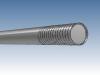
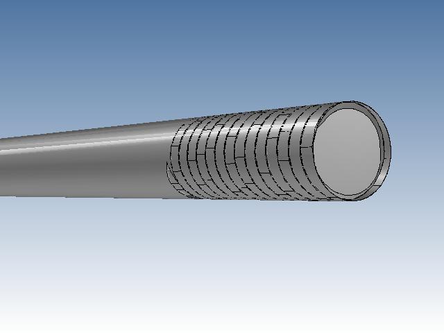
I tried changing kernels and that didn't work. I removed another extrude from the part and ended up losing the thread at that point & saved the file. I re-entered the thread but still can't add runout... tried .1 for runout after .5 didn't work but now the thread ends up with an error and disappears. A lot of waiting for a 1/4-20 bolt. I'll use it like this.
-
Why did the thread get buried inside the screw after I added runout? I've seen this problem before but don't remember if I found a way to fix it.
-
Ah yeah, that will help. Thanks, Cary
Doug
-
If I select a part and get properties> rendering I can increase surface smoothness. Is there a way to change this permanently so I don't have to change it every part?
Also worth noting... there seems to be no problem increasing this on many parts in a large assembly.
-
Template lines are just sheet curves. There is not a Template curve tool so that is why they would change as well. If you want to change specific lines on the drawing, you can select them all and change them at once or use the property eye-dropper to apply settings to other curves.
Cary
I can do that.
I just wonder... does anyone else have a problem understanding this?
There's a layer for sheet curves and the sheet curves (drawing elements) are on the sheet curves layer. I also have a layer for template but the template lines are sheet curves.
Before I have to try and understand the Styles and Layers dialog box anymore, I'll try to make time to look at CAXA.
-
Current Set meant the current settings. Open the Styles and Layer dialog. What you see in the Style and Layers for the drawing elements are the current setting when creating new drawing elements. It does not mean that these are the setting currently on the drawing for the elements. For example: You can create a sheet curve using .5mm solid on layer A. Then go to the styles and layers dialog and change both settings to .7mm and Layer B and hit ok. The sheet curve will not change to the new setting. If you draw a new sheet curve, it will use the .7mm and Layer B. If you go to the styles and layers dialog and select on Sheet Curves drawing element and then hit Reset, it will update all the sheet curves on the drawing to use the current settings in the dialog for styles and layers. I hope that helps clarify the issue.
Cary
OK, I got this all the way up until I hit reset. If I hit reset all of the lines on the drawing update to .7mm INCLUDING the template lines that are .030mm Solid (style) and Text (type). Note: the template was also locked and those were not sheet curves until I hit reset. Mine were set to template. Did I do something wrong or is this a bug?
Hopefully there's another way to change only the sheet curves or whatever element you want to change. If not, I don't see why you should be able to do this or what use reset has? If I wanted to change the first line I drew at .5mm (in your instructions) or many lines... there's no easy way to change them except to select each one individually and change them that way. Hopefully I'm just doing something wrong there.
-
When you right-click on a line and go to the properties, at the top you will see the Style and the Layer. You can set both.
The Styles and Layers Dialog will set the default behavior and you can also set all elements to use the current set styles (That is what the Reset button does (it reset all the elements in the drawing to the current set values). By the way, you should not need to close and reopen the drawing to see changes apply for new elements created. Existing elements will not change unless you reset.
Cary
Hi Cary,
I knew you could set the Style and Layer both in the properties but I was trying to set it permanently. So now I don't understand the reset button. I was assuming it resets everything back to the original IronCAD settings but then what do you mean by... "it resets all the elements in the drawing to the current set values?" current set - what is that?
I also noticed this long ago having a red layer when I draw a line it is black until I click off and or it redraws. When I did this and it didn't change to red I thought maybe I had to close the drawing and re-open for the settings to take effect, but now that you said I should not have to close and reopen I'll have to try it again to see why I thought that was what happened. I still think main my problem was trying to figure out what layers the different type lines are on.
Thanks
-
Well it appears to be working now. I guess maybe you have to close and re-open the file for changes to take place. Still I find it frustrating in this case that you can't tell what layer the line is on so you just have to change layers until you get the right one and on top of that have to close and re-open the file each try. This should probably be filed as a problem.

IronCAD on Windows 7 32bit vs 64 bit and XP
in General Discussion
Posted
Mark,
Obviously you need a computer that will run a 64-bit OS if you want to install one and I think any 32-bit version of Windows will only support up to 4GB of RAM at the most. I used Win XP Pro 32-bit until I ran into poor performance and needed more memory for larger assemblies. Now there's a lot of info out there comparing performance of the different versions but I don't think you need to look very far. I would just install Win7 Pro 64-bit since that is about the latest and greatest.
Here's a couple links that might help.
http://windows.microsoft.com/en-US/windows...asked-questions
http://msdn.microsoft.com/en-us/library/aa...8(v=vs.85).aspx
http://www.ironcad.com/support/community/i...owtopic=6123&hl