


Mike Allen
-
Posts
1,417 -
Joined
-
Last visited
Content Type
Profiles
Forums
Blogs
Downloads
Articles
Gallery
Posts posted by Mike Allen
-
-
Thanks, Kevin! That fixed it.
-
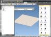
In previous versions (I started with version 4, I think), when an assembly was selected in the scene & I dropped a part from a catalog into the scene, that part became part of the selected assembly.
In IC2013 (build 11090), when I drop the new part, the selected assembly is deselected & the part is added to the end of the scene browser list.
Is there any way to get the old behavior back, or do I have to add a step to my workflow (drop the part & then drag it into the desired assembly)?
-
Thanks - I did try that. Changing the threshold number doesn't affect the current scene. I've since turned the feature off.
I can see the value of having the Large Assembly Mode to speed things up on big files while you are looking for what needs to be worked on - but it would be much more useful to me if it would turn off when the number of unsuppressed parts falls below the threshold.
-
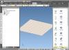
I opened a big file in IC2013 & it shifted me into Large Assembly Mode. So I thought, "fine - I'll just suppress everything but the assembly I want to work on & it will put me back in normal mode." But it didn't do that (maybe it wasn't the intention of the feature.)
I've been looking for a way to toggle out of this mode, so that I can make some changes at the shape level, but there doesn't seem to be an obvious way to do this. The feature doesn't seem very useful to me, if the only option is to deselect the threshold number of parts (or increase it), close the scene & reopen it - since the scene took several minutes to open.
Does anyone have a way to get back to normal editing mode after a scene opens in Large Assembly Mode?
-
It's possible that this might be a more extensive issue. I thought it might have been my imagination, but it seems more common lately to have extremely small imprecisions crop up - 99.99998, instead of 100, for example. I haven't had time to document it, however. It seems to happen mostly when sketching (I think.)
-
It's been our experience that we only need the distribution DVD for updates if we originally install from the distribution DVD. Since we started downloading the installation files & installing from a single network location, we have never been asked for the distribution DVD when installing updates.
-
I would vote for Black, except that some of my inactive catalog tabs tend to change to white text on a gray background, making them almost impossible to see.
-
It's possible to show hidden lines on just one part in a view using Edit View Curves. (The view must be in precise mode.)
1) Show hidden edges in the view.
2) Edit view curves.
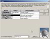
3) Set Filter Edge Visibility to "Hidden Only", Select Edges to "Parts" & Layer to "HiddenAnnotations"
4) Select the parts where you want to hide the hidden edges.
-
If you do the smart paint the other way around - select the part at the part level & smartpaint black, then select the faces & smartpaint brass. When you subtract the letters, all of the newly-exposed faces will be black.
-
I haven't tested this, but could you drag the assembly into a catalog, change your Parts option to "Create facet part", then drop the assembly from the catalog into a scene?
-
Dragging a color/texture to the background didn't work for me until I switched my rendering driver type from OpenGL2 to DirectX. Now it works with all 3 driver types.
-
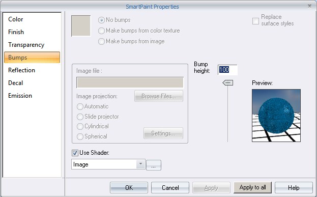
Black doesn't work, but very dark gray does. Also, you have to turn off "Cast Shadows" for the light (bumps don't show up in the shadows.)

-
I'm wondering - what would happen if you made the color of the scene light black? It's possible that the only requirement is that the light is on.
-
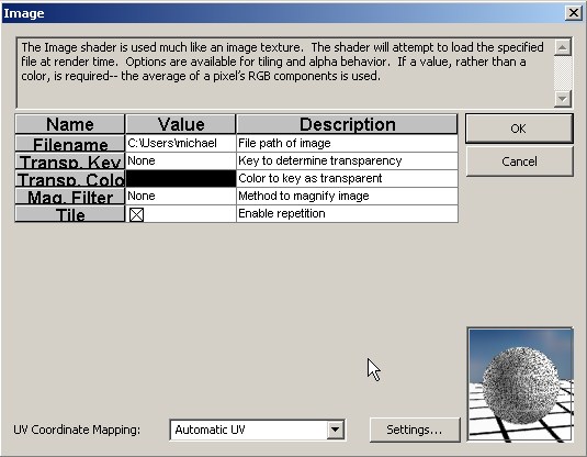
You need to turn on at least one light in the scene. Then use an image shader for the bumps (Automatic UV) appears to work best.
-
Set up a scene the way you like it & save it as a template. All of the Show settings are saved with the scene.
-
1. TriBall
2. Window Zoom
3. Fit Scene
4. Extrude Wizard
5. Offset
6. Project
As far as improving process of commands goes:
All direct entry fields (distance, radius, etc.) should remember the previous setting within a drawing session. (For instance, if I use an offset distance of .125, the next time I use Offest, it should already be set to .125.)
All button dropdowns (even on the S menu) should remember the last-used tool (and there should at least be a setting to make wizards the default.)
-
We have had luck with this: http://www.howtogeek.com/howto/windows-vis...-menu-in-vista/ - It's a registry hack that adds "Take Ownership" to the right-click menu. Once it's installed, you "Take Ownership" of the stubborn file, then delete it.
-
...
Hey Kevin, how did you manage to post this from the future? Is IronCAD working on a method of time travel?

-
-
If the default behavior is to orient the anchor to global, then this t-base part is apparently the only part in our catalogs that is working right. With any other part, the anchor point of the assembly is taken from the first part you select.
-
I rarely use 3D Smart Dimensions to drive part movement, but I think they generally work fine as they are. The only thing that bothers me, is when I use an angular Smart Dimension to constrain two shapes, I'm unable to predict which direction it will rotate when I change the angle. For instance, if I start with the constrained edges at 90 degrees & change the angle to 45 degrees - as often as not, it will rotate 135, or 225, or 315 degrees (see below topic.)
http://www.ironcad.com/support/community/i...?showtopic=7066
Most of the time, however, I use Smart Dimensions as a standard dimensioning tool, not as a constraint.
-
...
- I can not get a rendering bigger then the "screen size" to come out without some strange artifacting in it, like tiny red dots.
...
If you are generating an image that is bigger than your screen, there will be some artifacts in the render output window (since IronCAD is scaling the image to fit inside the window) that don't actually show up when you save the image.
-
-
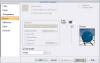
I'm not sure about the thread representation, but to dimension to the extreme points of the slot, look at the left side of your screen (where the Properties Browser lives) and either check the checkbox that says "Include geometry points," or set the Snap To: drop down to "Geometry Points."

Rotate Text Box in Drawing?
in General Discussion
Posted
I used to be able to rotate text in a Drawing by using Rotate Curves from the Sketch tab. In IC2013 (build 11090), that tool isn't available when I select text.
How do I rotate my text objects in IC2013?