Mike Twining
-
Posts
910 -
Joined
-
Last visited
Content Type
Profiles
Forums
Blogs
Downloads
Articles
Gallery
Everything posted by Mike Twining
-
I would try throwing 2900 into the USERVA (the opposite end of the "approved" spectrum) and see how that works. With the 3030 number, your memory allocations are not that much different from just using the /3GB witout the USERVA. It sounds like you still have quite a bit of paging going on when starting your apps. You may want to open up taskmanager and watch the little yellow line on the performance tab when you start up applications... if you see some ramping up and then dropping off, you should give the system (or kernel) some more memory.
-
I too use the Quadro FX550, although I don't seem to have any issues with the /3gb setting (although I only have 2G of RAM). I'm currently using the 81.76 driver if that helps.
-
I don't know if it is either too involved to too time consuming, but if you feel you are having the above problem, there is a setting (USERVA) I believe that goes with the /3GB switch, which allows more control over the Windows/Application memory split. It'll allow you to fine tune your memory needs. As for the original post... ...the only thing I can think of is have a look at your pagefile settings. Are they rigidly defined (and if so, what are they set at), or is windows allowed to set them automatically? What else are you running in parallel with IronCAD, and what is using up all the memory. Truy running taskmanager (run->tskmgr.exe), selecting the Processes tab, and sort by Mem Usage (just click on the column header to sort). What is that showing you.... Right now (without IronCAD running), 4 of the top 5 memory hogs on my machine are system processes and IT oversignt/tracking software.... the other one is Outlook. I have been known (don't tell IT) to kill a tracking process to weasle some more power from a lagging machine, but you will need admin rights to do such things. The Windows Search Indexer is also a hog (that is one of my top 5). Personally, that never has to run if you ask me....
-
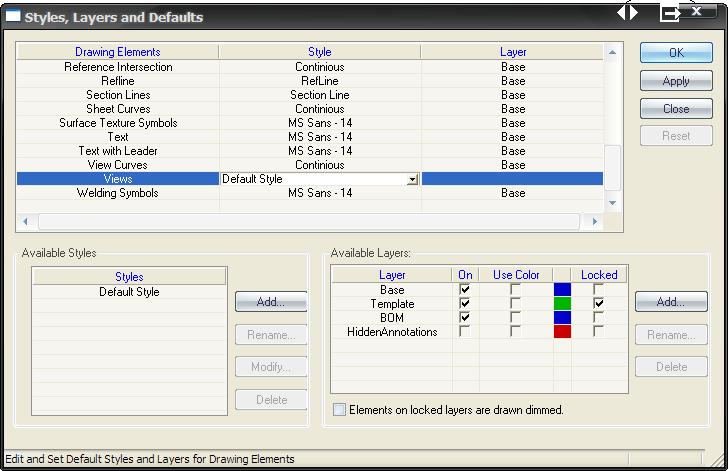
I don't know anything about the problem you hare having, but the list of Styles come from the Styles & Layers dialog under the "View" section. FWIW, the asterics generally means that it is MOSTLY the listed style or BASED ON the listed style, just with some user directed changes (in this case perhaps the defulat is to show hidden lines, and you have selected to NOT show them... that would result in an asterics).
-
I am still curious how 0 depth is defined.... any word on that?
-
One of my co-workers here is attempting to make a broken out section on an ISO view, and he was asking me how to do that.... I know what he is trying to acomplish, but the whole idea of a broken-out section on an ISO (within IronCAD at least) makes my brain hurt, and so I have a few questions: 1) How is the "origin" defined for a broken out section view (i.e. how do you define where 0 starts with relation to the depth)? 2) Generally, one selects the depth of the broken out section cut from a projected (profile) view. If you are attempting to make a broken-out section on an ISO, does that mean you must select the depth from another ISO view whcih is perpindicular to the view you are trying to make? 3) Should the broken-out section even be an option for ISO views... and then... how do you even define what an ISO view is since I can position my "front" view in any orientation that I choose.... ...anyone with some insight? I think for the time being, we will just make a configuration which has the "broken out" section cut with some H_Shapes... but the whole idea behind his quest makes me go "hmmmm?".
-
I was merely refering to the ...\IronCAD\IronCAD\... directory path, and playing off the other repeated redundancy post . ...and as they say, "Any joke you need to explain is no joke at all". I'm a lot funnier in my own head... I swear!
-
You files are already saved in: C:\Docs & settings\[username]\Application Data\IronCAD\IronCAD\10.0\Customization\ (where the annoying .tbc file used to be) In there you will see 4 .xml files. Simply distribute, or copy over and you are good to go. (P.S. Is there another redudnancy issue?) (P.S. Is there another redudnancy issue?)
-
Those are just vectors, and are "normalized" when computed. In reality, the only thing that matters is not the value of the numbers entered (when defining a vector), but the relationship (or ratios) of the values entered.
-
Oddly enough, if you create the part as Cary did, then delete the original shape, you end up with the just the desired part.... which somehow remembers everything about the original shape it was built off: If you stretch the handles outside where the original shape was, the part fails, and if you stretch the handles past the other end of where the original shapse was, the face flips... Unfortunately, there is no way to modifiy or edit the original (source) shape or the chararicteristics after deleting the shape...but if you like what you have, it is a nice trick!
-
FYI All- As previously posted, I recommend re-createing your templates in V10. It appears (for me anyway) that any text boxes with variables (i.e. $PRP.......), once saved in V10 (and then the variable display resorts back to the code $PRP....) and then updated again, the text value becomes static (i.e. just text, no longer a variable link).
-
I know I ask every release, and the answer is always the same, but: Should I re-create our drawing and BOM templates from native V10 "blanks" or can I just save the existing ones as v10 files? ... and as a follow on, how do you guys establish "new" blank files. If you are just re-saving old ones in the new format, I feel like I can do the same and save myself some work.
-
That's funny, cause my days with AutoCAD have trained me to try to make a keyboard shortcut for everything. Must be a fancy-shmancy tablet thing....
-
Now I just wonder how you are going to count all those nails that end up bent....
-
I don't know what your model tree looks like, but could you make an assembly of all the cut pieces (one assembly per sheet of plywood) and then treat the assembly as a part (for the BOM purposes). That'll count correctly as long as you put the same part number in for all your linked full sheets (and use the same part nubmer for your assemblies of cut sections of wood).
-
If you run IronCAD on a laptop with Windows XP; it turns out that the power configuration you choose has a lot to do with how well your machine performs. The whole article can be found here: http://www.orthogonalthought.com/blog/inde...power-profiles/ ...The short version of it is: If you want max performace out of your laptop while it is plugged in, set the Power Configuration to "Home/Office Desk". If you want max performance from the processor while on the battery (and you don't need it for long), set the power scheme to "Always on". Anything else and Bill Gates is throttling your CPU to save (battery) power.
-
All of your analysis is correct. 1) Your problem is XP Media Center... it being the Win98 of the newest releases: it won't benefit from the added memory because 2) the /3gb switch does nothing to this version of windows. You need XP (Pro). You are basically driving a Ferari there, but is has an Fiat engine in it. Spring for the extra $200 and get your V12 back! EDIT: Well, upon further research, it appears as if Microsoft is inconsistent in determining which OS's will accept (succesfully) the /3GB switch. Some of their pages imply XP Pro only (for the XP family anyway) and some say all versions of XP (whcih would include Media Center). Personally, I am still inclined to believe that it is XP Pro only....but I am no longer as sure.
-
How Do I Get The Number Of Holes On A Bom?
Mike Twining replied to Thomas Wehle's topic in General Discussion
..well... technically you can get these things into the BOM, but unless you can do some programming, it won't be automatic: You can create custom properties for parts, and have the info you desire reported in the custom properties. From there, you can set your BOM up so that one of the displayed columns will show your custom property information. Of corse, any changes made to the 3D model will not be reflected in the BOM (or custom property) without you explicitly changing the custom property valuse themselves. The hole table route is much easier (and harder to screw up!) -
Since it is a slow forum day, I thought I would stir up some communication: The basic question is, do you use IronCAD's 2D cabability? How often? If no, why? I know this is supposed to be some paperless society, but I have yet to deliver a customer or fabricator any 3D cad file. To date, everything has been an electronic copy of an old-school 2D drawing.... to the point, where 3D models are "hacked" to ensure the 2D drawing is accurate. To me, this seems totally illogical, and unnecessairy, if not unavoidable. As old-school as this may be, it is a necessairy evil that I am afraid will (again) not get sufficient attention from the IC developers. Where on the fence are you?
-
Yeah... think of all the maintenance you could do to screwed up parts by helping out the poor souls stuck with SW!
-
Got hyperthreadding enabled? Running 32-bin Windows with the /3GB? Back in the early days of multi processors (or cores or whatever), I used to use a tool which would allow you to quickly and easily set process affinitys (lock in what currently running programs would use which processors)... the idead being you put everything on one processor and IronCAD on the other. A quick google returns sooo much I can't find what it is I used to use, but it worked really well (it was noticeable). If you have never set an affinity before, you do so through the taskmanager (taskmgr.exe): Under the "Processes" tab, when you right click on a process you have a "Set Affinity" option. Unfortunately, it only address the individually selected process, and the settings are NOT maintained when the process is ended (i.e. IronCAD is closed). Another thing I have seen in the past is performance issues when a program is not running on the "primary" monitor (in a dual monitor setup). I would have assumed that these have been all but solved with updated video drivers and such... but it is something to try.
-
Hahaha! I missed the post when it was new (or maybe I skipped it cause I thought there was too much reading involved), but I gotta give it an A+ on the geek humor scale!
-
...agreed. I would have thought that a Parasolid model w/ a Precise view setting SHOULD have produced the same results (a nice smooth curve).
-
I too have had success re-setting the surface smoothness of 3D models to enhance the quality of the 2d drawing, but if I recall correctly, that was in an ACIS-Draft situation (I never had to change it twice though...). Like Tom mentioned, the slider is there for play, but you can enter any number you want into the surface smoothness setting in 3D (and also like Tom, I am a fan of a setting of 200). I believe 72 is the max on the slider bar... but you can do way better than that. I would also play a little with the Rastor/Vector (assuming raster would be better for your arc) settings on the printer (FIle->Print). Lastly, see if the printer settings (er... printer properties) themselvs are affecting you at all.
-
Is the issue with how it displays in the drawing (on the monitor) or how it prints off the printer?