
Jonas@Solidmakarna
-
Posts
2,269 -
Joined
-
Last visited
1 Follower

Recent Profile Visitors
2,686 profile views


Jonas@Solidmakarna's Achievements
")
TriBall (9/9)
134
Reputation
-
Here is a page with a bunch of useful shortcut keys explained (auto-translated into English, but quite ok). https://en.solidmakarna.se/supportblogg/kortkommandon-i-ironcad
-
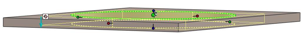
Cannot return to state after part becomes transparent
Jonas@Solidmakarna replied to tgjang's topic in General Discussion
Have you tried to cancel the new transparency setting that can be applied to the parts (it's not a color setting)?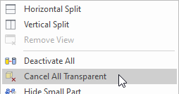
-
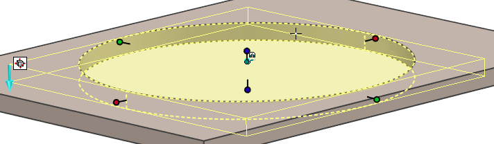
Creating a smart dimension on hole feature.
Jonas@Solidmakarna replied to tgjang's topic in General Discussion
There are at least three options! Kevins suggestion is usually the best. Remember that with the [Shift] key, you will always "Snap to Center" in many commands. But you can also; Rotate the camera to see the center of the hole placed in front of the "hole depth" (mantel surface). Typical case on thin models, like Sheet Metal parts. Hold down the [Ctrl] key when the mouse cursor is placed "within the Sizebox, touching the Shape" to place a Smart Dimension from the Anchor Point. A "cyan blue little dot" will appear "behind" the Anchor Point (hint hint, ER please! ). Since a Cylinder Shape dropped from a catalog usually have the Anchor Point placed in its center, it's a useful option. I most often use this when creating parametric models with some locked Smart Dimensions acting as constraints. I usually prefer controlling the Anchor Point (which always controls the geometry) rather than a green face/edge/vertex of the Shape.
-
Adding 'empty assembly containers' to scene tree.
Jonas@Solidmakarna replied to HDEAR's topic in General Discussion
I agree that we would love to see videos about many of the new functions in the What's New documentation. Kevin has added some videos here at the Community too. The new Assembly structure function is "simply" that you can click on the Assembly button and create an "empty" Assembly.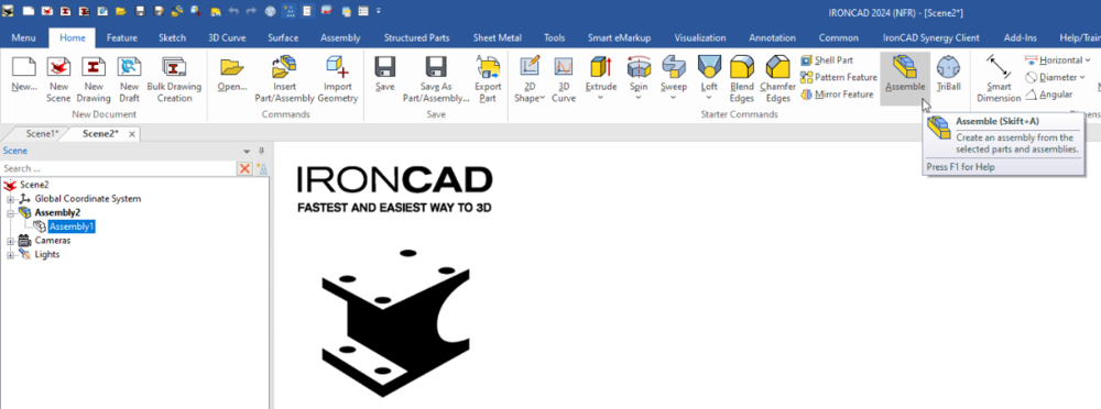
-
According to ISO 5455, there are a certain number of View Scales available. But it can be useful to have more scales available in the drop down menu, which is managed in the MS Registry. Here are some MS Registry (*.reg) files which adds more View Scales (32 in total, like in the picture above) to the ICD, depending on version: IRONCAD v2022 IRONCAD v2023 IRONCAD v2024 Download and run the MS Registry file. Answer Yes, OK, I'll do, All right just stop asking and so on ! Be aware that manually editing the MS Registry can lead to issues. It's good to always open/edit a *.reg file in a text editor to get a hint of what it will do, before you run it.
-
displayed filename as a :1 - what does this mean?
Jonas@Solidmakarna replied to RLUXTON's topic in General Discussion
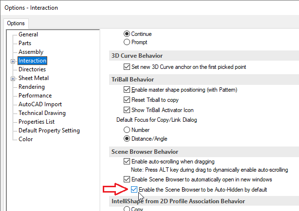
It's because the Scene Browser has been set to be undocked by default or when a new scene is opened, which is also shown in the image, even though I don't know why it should add this :1 to the file name just because of this. To solve this, double click at the top of the Scene Browser, to dock it back into the program window. Then close and open the file again. -
If you can ignore the effect on other possible drawings etc, the absolute fastest way must be this! 1) Select the object(s) 2) Drop the ICM Set Include in BOM Status (left mouse button toggles all ON, right mouse button toggles all OFF) http://ironcad.it/learnICM/en/utils-catalog/010_set_include_in_bom_status/
-
Single line font for laser profiling of part numbers
Jonas@Solidmakarna replied to dbarber's topic in General Discussion
Here are some that we mention on our support blog (in English) - https://en.solidmakarna.se/supportblogg/20-gratis-typsnitt-for-laserskarning Though I'm not sure about if any of them is a true "single line". -
I see, that was far more complex! Well, then that catalog won't help of course. You'll probably need to make a Sweep shape from 3D Curves or maybe it's possible to build "good enough" even with quite simple drag-and-drop shapes. Perhaps also a Structured Part where the curves are associated with some of the edges from a "base shape". At the moment I don't have time to look at it, but I'll see if I can try quite soon.
-
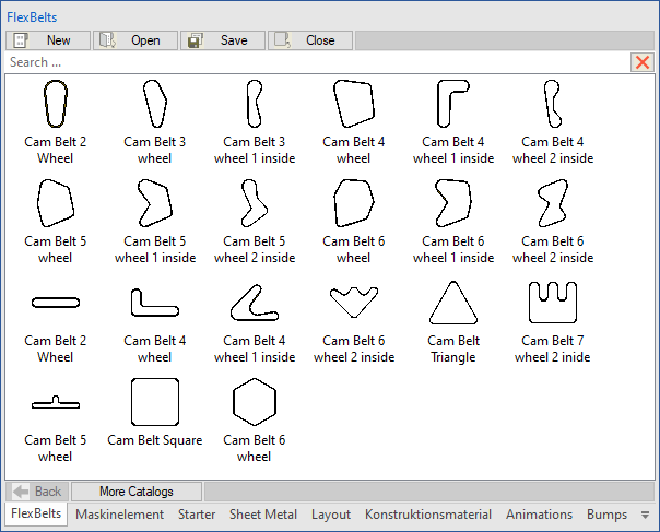
https://community.ironcad.com/index.php?/topic/11939-flexshapes-belts/ Here's the old post. Not that old though
-
Maybe this catalog can help you out? FlexBelts.icc It's a catalog (saved in v2023 PU1) with various "belts" that I made many years ago. There might even be a topic/post with more information about them here somewhere that I can no longer find.
-
Thanks Kevin. Another thing I didn't know about this is the fact that you can also select objects that are behind the transparent object! So in the video, you should be able to select the various PCB models that you see inside.
- 1 reply
-
- 1
-

-
We placed an ER for that a while ago, Ticket #10643 - ICC, being able to store/drop only the Material value to/from a catalog. It would be a great function to change material without changing color.
-
It was probably because of this setting, why resetting the registry also solved this problem. Back in the days (around v5.0) the Scene Browser wasn't shown by default and some didn't even know there was a tree structure for the models you made!
-
Question. When saving, construct the filename.
Jonas@Solidmakarna replied to tgjang's topic in General Discussion
Cary, you can have a look at Color separator for Tree Items Ticket #3552, which includes three other ER's for the tree item display. Add Tree Item Display separator - Incident # 103454. (has no ticket ID #) - what is being discussed in this post. Wants tree display option to show also as part name tooltip - Incident # 104027. (Ticket #1348) Items inside Patterns doesn't make use of Tree Item Display Type - Incident ID#: 108363. (Ticket #3483) I also think these tickets are related and worth looking at; Choose tree item display type - affect the search result in the search tab - Incident # 110494. (Ticket #4758) Filter by color in Scene Browser - Incident # 113335. (Ticket #7130 - similar to #3552)